
Contents
This is the 1st update of the robot since I last posted on this project (I’m rather busy with school & other stuff). In this update, I have roughly sketched out the design of the robot, how it would function and also designed the frames of the robot & the body plate of it. (using SketchUp)

Design Sketch
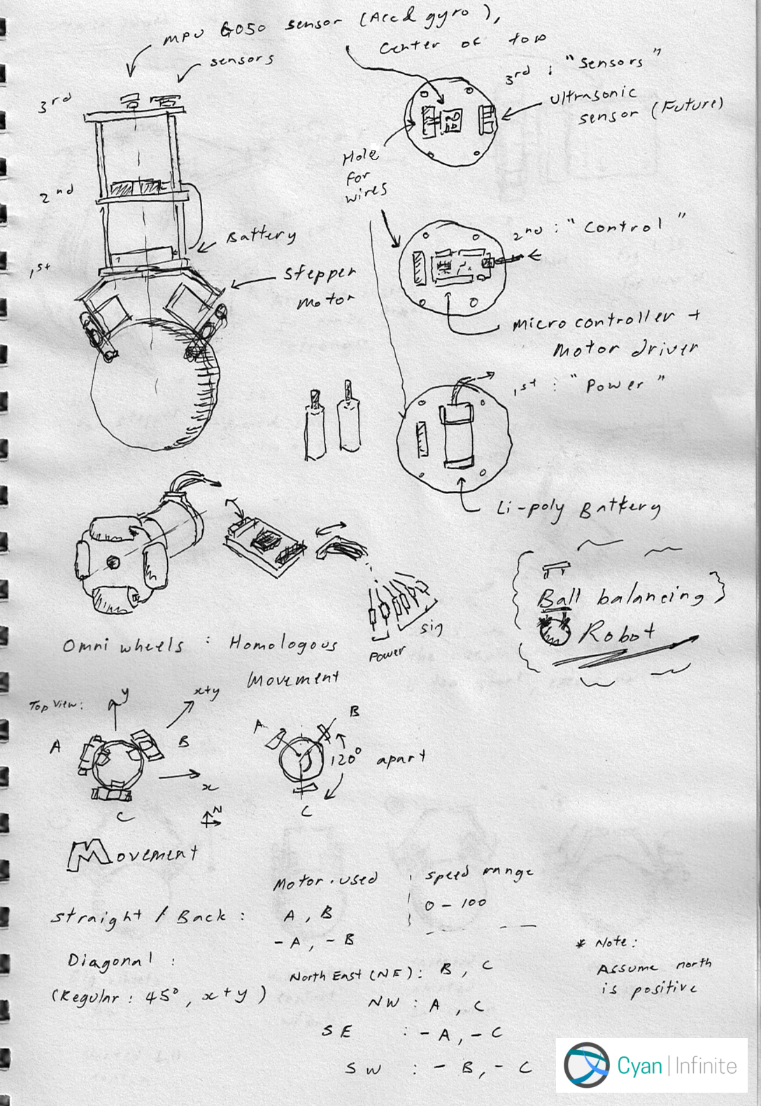
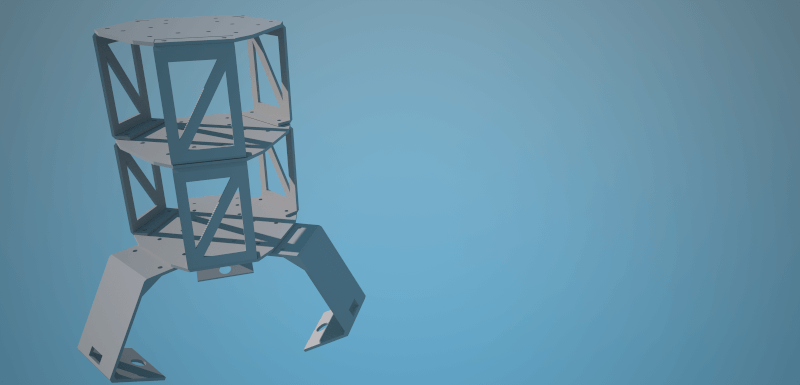
Here are some sketches on the robot design & some of its functions, like how is it going to move. The robot will have 3 levels (separated by standoff screws I have decided to design a spacer frame myself instead) with each having their own functionality:
- 1st Level (Power): This is where my batteries will reside in.
- 2nd Level (Control): The micro-controller (most likely Arduino Uno) & the motor driver will be here.
- 3rd Level (Sensors): The sensors for the robot will be located here. Most likely be using the MPU6050 (Accelerometer & Gyroscope) sensor. When everything is working fine, I will add an ultrasonic sensor too.
The robot will also be able to move freely in 2 directions simultaneously, thanks to the omniwheels. Not only that, it too can rotate on the spot. As for how the wheels is going to contact the ball, I choose the 1st one out of the 4 I have drawn as it have better contact & control of the ball.
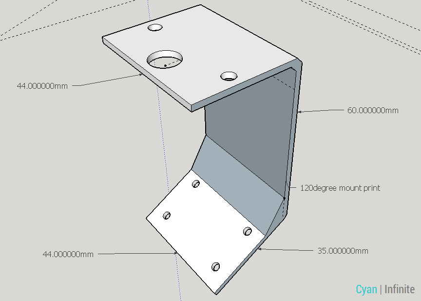
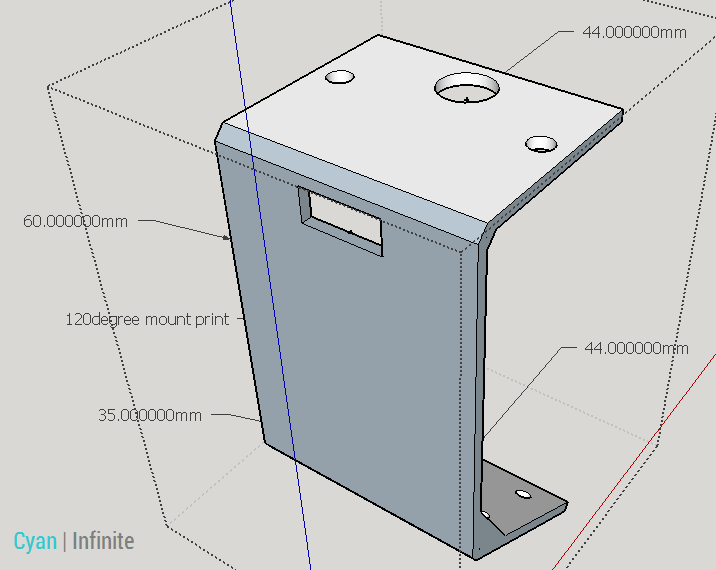
I will be using a 5V Stepper motor & the motor driver for control, and will be mounted diagonally to the slanted frame.
For the frames, it will be 2mm thick and will be using a fillet design in the interior of the frame as to strengthen the structure of the frame. (Thanks for the advise, Abram!)
For the power part, I’ll most likely be using a Li-poly battery as the have a higher capacity compared to normal 9V alkaline battery. For the connection between the battery & the micro-controller, I have to modify the power jack a little as I want to power the stepper motor drivers seperately & not from the micro-controller. (As these motors may pull too much current —> Board fried). So, I will solder 6 female jumper wires to the power jack.
Body & Frame Design
I used SketchUp to design the various frames & body plate. Below are some images of the design.
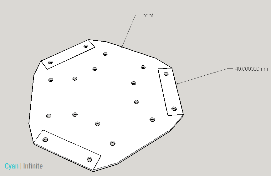
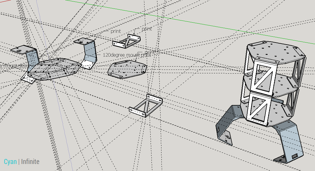
Here is a render of how the robot will look like. (Only the frames) I’ll be uploading the sketchup file onto Github soon, along with the STL files once I have finalised everything.
Part list
Here are the parts I most likely be using:
- Arduino Uno x 1
- 5V Stepper Motor x 3
- ULN2003 Stepper Motor Driver x 3
- 48mm Omniwheels x 3
- MPU6050 Accelerometer & Gyroscope Sensor x 1
- Li-Poly batteries (Yet to decide rating) x 1
- Modified battery barrel jack x 1
I have purchased some of the parts, but have yet to test them out.
That should be it for this update, the next update should be more focused on the 3D printing & testing of the parts, and the finalisation of the design.
To-Do list:
Write out Main ideaDesign the robotSketchComputer (SketchUp)
Write out Part list- Purchase components (sensors, wheels, etc.) [partially done]
- Test out components
- 3D print main body & parts [partially done]
- Mount components onto body
- Code the bot
- Run it!