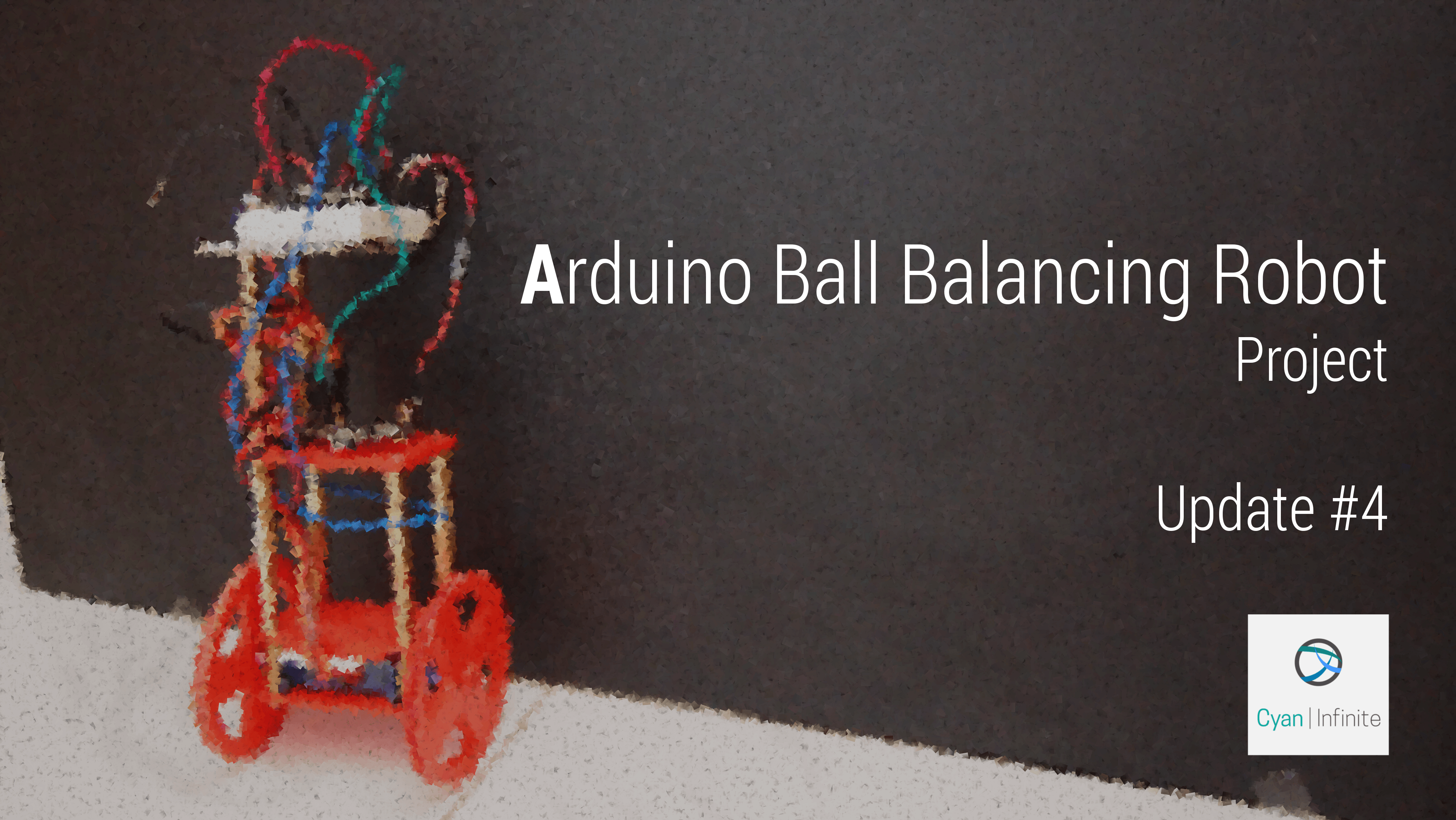
Coming up, another short update on my self balancing robot! In this update, I focused solely on improving the connections, structure and placement of the components on the robot. (P.S. I have uploaded the SketchUp & STL files on Github. You can check them out now!)

Update 4 – 01/11/15:
(This update is more on the hardware aspect)
Structural
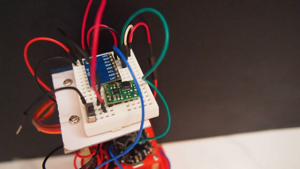
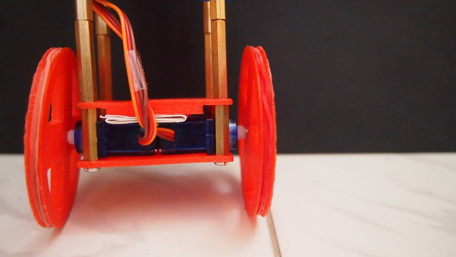
- For the robot, I decided to add one more level above the top plate I have designed as to allow the sensor to be more sensitive to changes. (I assume the sensor will be more sensitive as the torque of the robot will be much larger as the sensor is further away from the pivot (wheels) of the robot.)
- The distance between the centre plate & top plate will to small to place anything in between, so I added 4 more stand offs to make it more “spacious”.
- 3D printed the wheels for the robot, which I got the design from Thingiverse. (I forget the link I have gotten the wheels from, but once I remember, I will place it here. Sorry!)
For now, the wheels look kind of slanted to one side. I will rectify this problem soon (Maybe by printing a new set of wheels or buying it instead.)
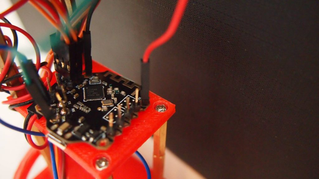
Connections
As the connections of the robot was extremely messy, I decided to rewire them so as to fit a nicely (or should I say, ‘nicer’) on to the robot. Replacing long wires with short ones, taping certain group of wires together, etc. Other than that, I also created a 2 to 1 power bus for my servo motors as to reduce the number of wires I’m using.
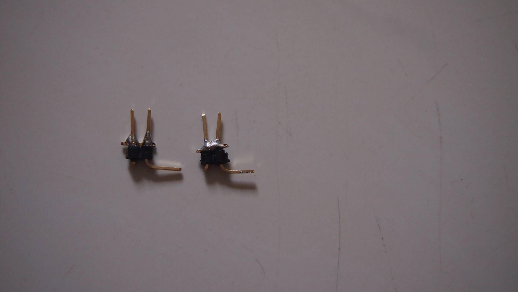
I used a 2 pin male header pins to create the bus, by shorting one end of the header pins. (I cut off one part of the pin and soldered it between the pins of the other side.) To prevent potential short circuit with other electronic components at the place I soldered, I put a small shrink wrap around the exposed soldered area. Here are a few images of the final bus, under a magnifying glass:
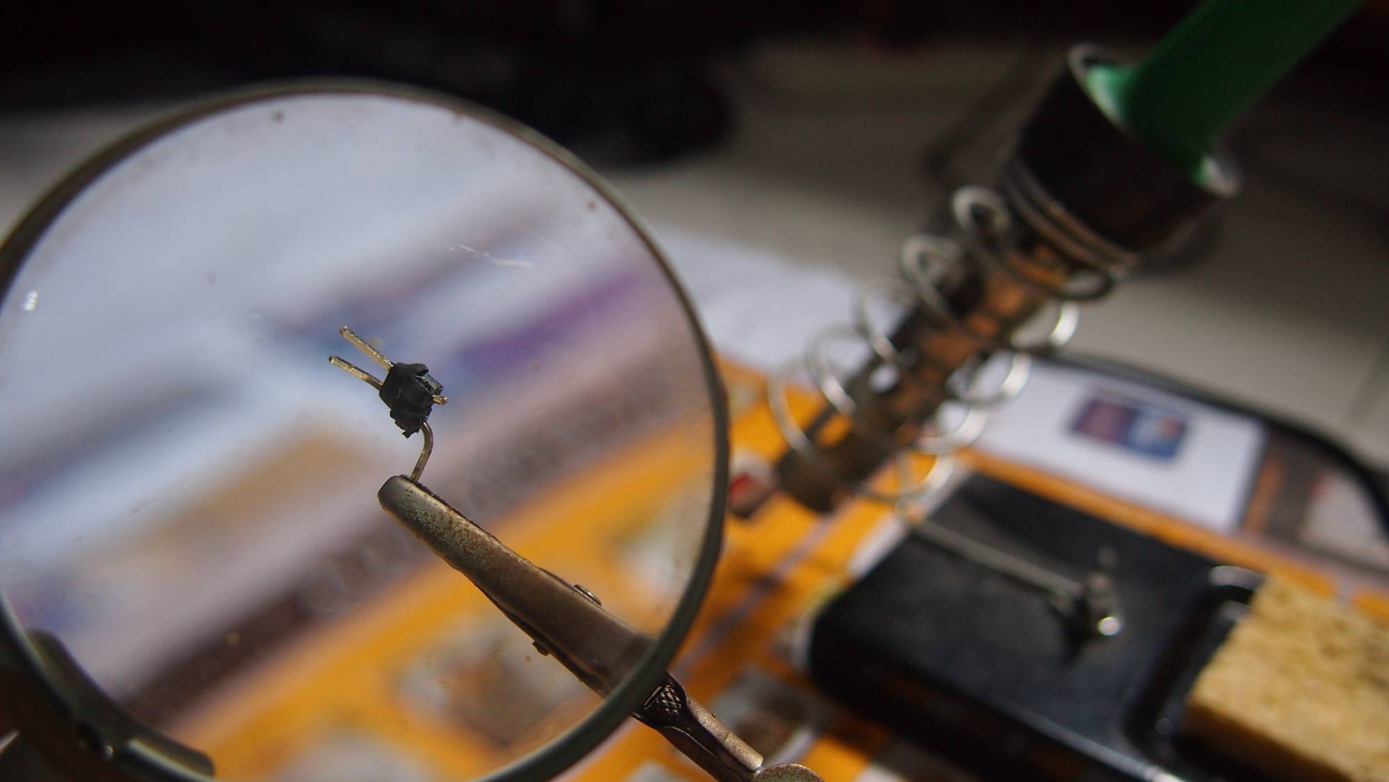
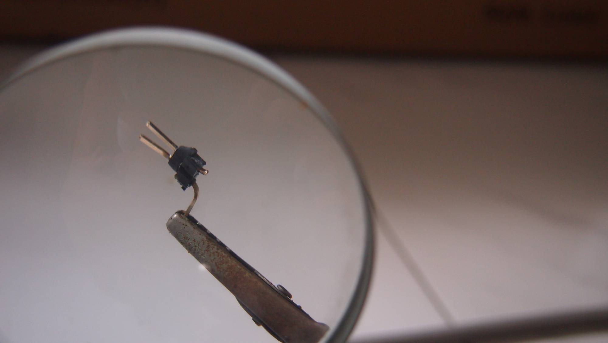
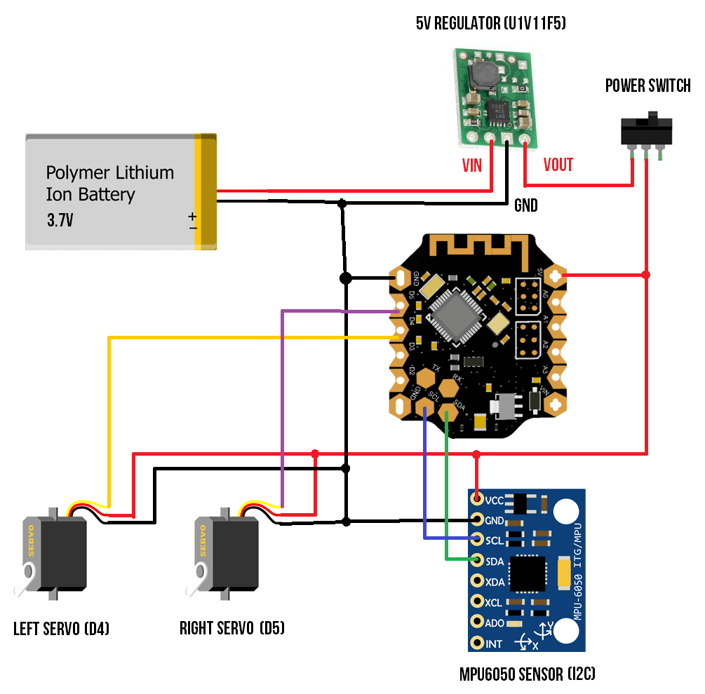
I bent the end of the single header pin as to make it easier to connect the wires to the power bus. Moving on, we will look at the schematics of the robot, as shown below. I will be using a 5V voltage regulator to step up the voltage of the 3.7V Poly-Li-Ion battery, and a power switch to turn the robot on and off.
In the next update, I’ll probably focus on the programming aspect of the robot, combining the gyroscope and accelerometer values, implementing filters, etc. (Where the fun comes in!)