Contents
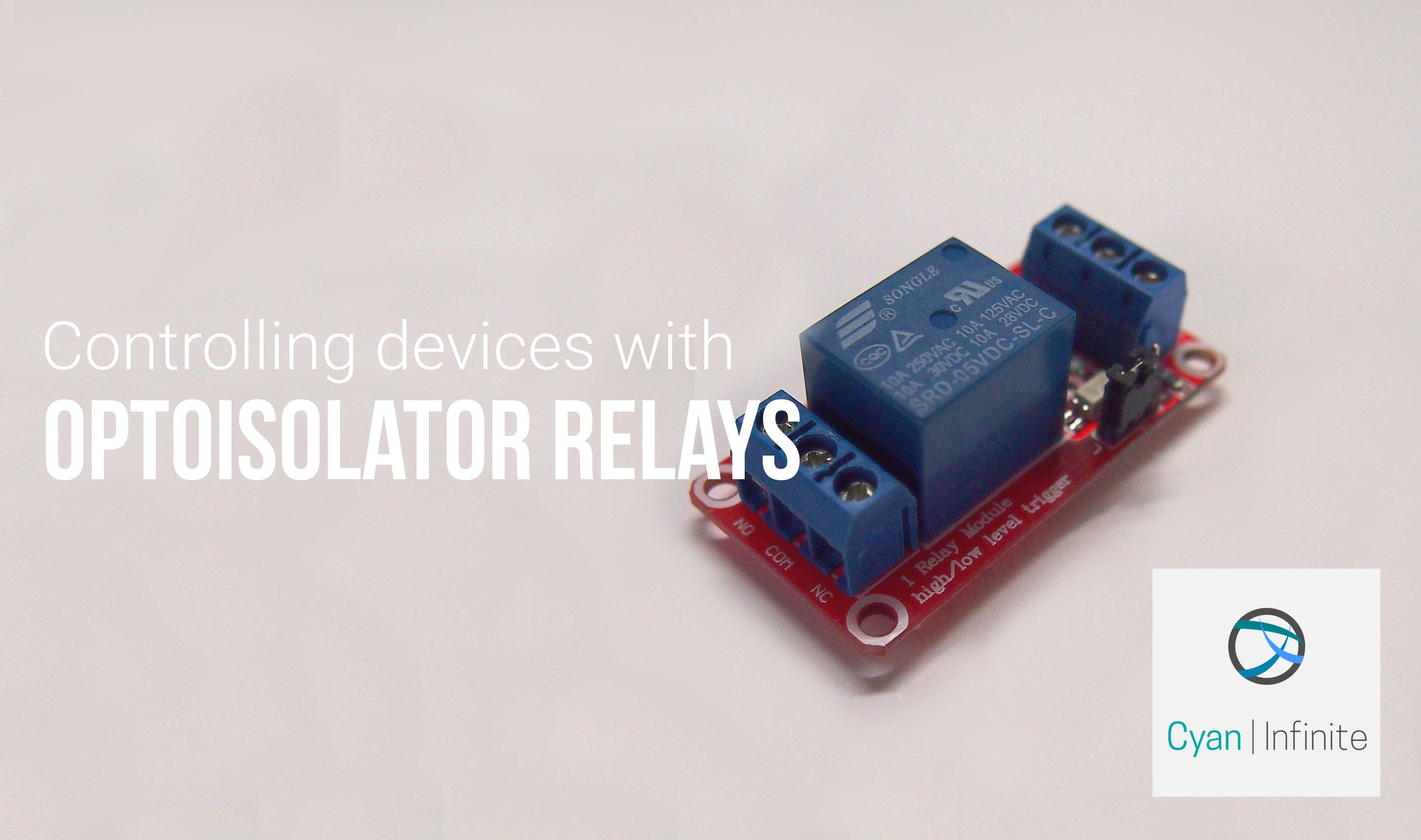
Need to control devices that has high power or does not have the same power rating as the Arduino? Using an optoisolator relay is one wokr around you can choose to approach this issue. With that, this tutorial will give you a short insight on how one would be able to interface this with an Arduino.

Normal Relays VS Optoisolator Relays
What is the main difference between a normal relay and an optoisolator relay? The difference can be seen from the name: normal relays would have the control circuit and load/device circuit connected directly to the relay itself. Whereas for optoisolator relays, the control circuit is isolated from the load/device circuit. This type of (optoisolator) circuit is commonly used when one wants to isolate high current load circuit from the control circuit. (If a normal relay is used, it is likely the control circuit will be fried if there is a sudden current spike in the load circuit, which may go through the relay to the control circuit.)
How they work?
As the name suggest, optoisolator relays worked by controlling the state of the relay using light.
Pinouts
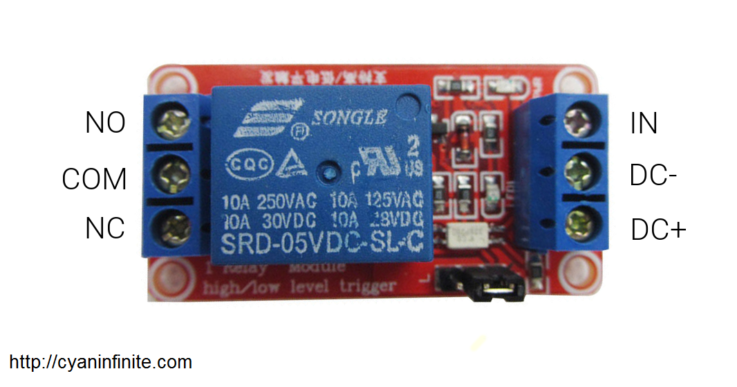
There are 6 pins on the relay, 3 for the controller circuit, and the other 3 is for the load circuit. Below is a summary of the abbreviations & its meaning:
| Abbreviations | What it (might) mean | |
|---|---|---|
| “Control Circuit” | NC | Normally closed |
| COM | Common Source/Ground | |
| NO | Normally Open | |
| “Load” Circuit | IN | Input (trigger) signal |
| DC- | Power Source Ground | |
| DC+ | Power Source VCC |
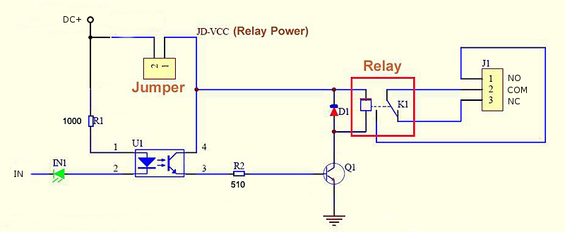
The internal connection would look something like this:
Getting started
We’ll test the relay by making the relay toggle its state every 0.5 seconds, which will in turn toggle the LEDs on and off respectively according to the connections to the relay.
Demo
Parts required
Not much part is required, though you can choose to use the Arduino Uno instead of ATtiny85.
- ATtiny85 USB Breakout
- Optoisolator Relay
- Jumper Wires (Male/Female)
- Mini Breadboard
- LEDs X 2
- 330Ω Resistors X 2
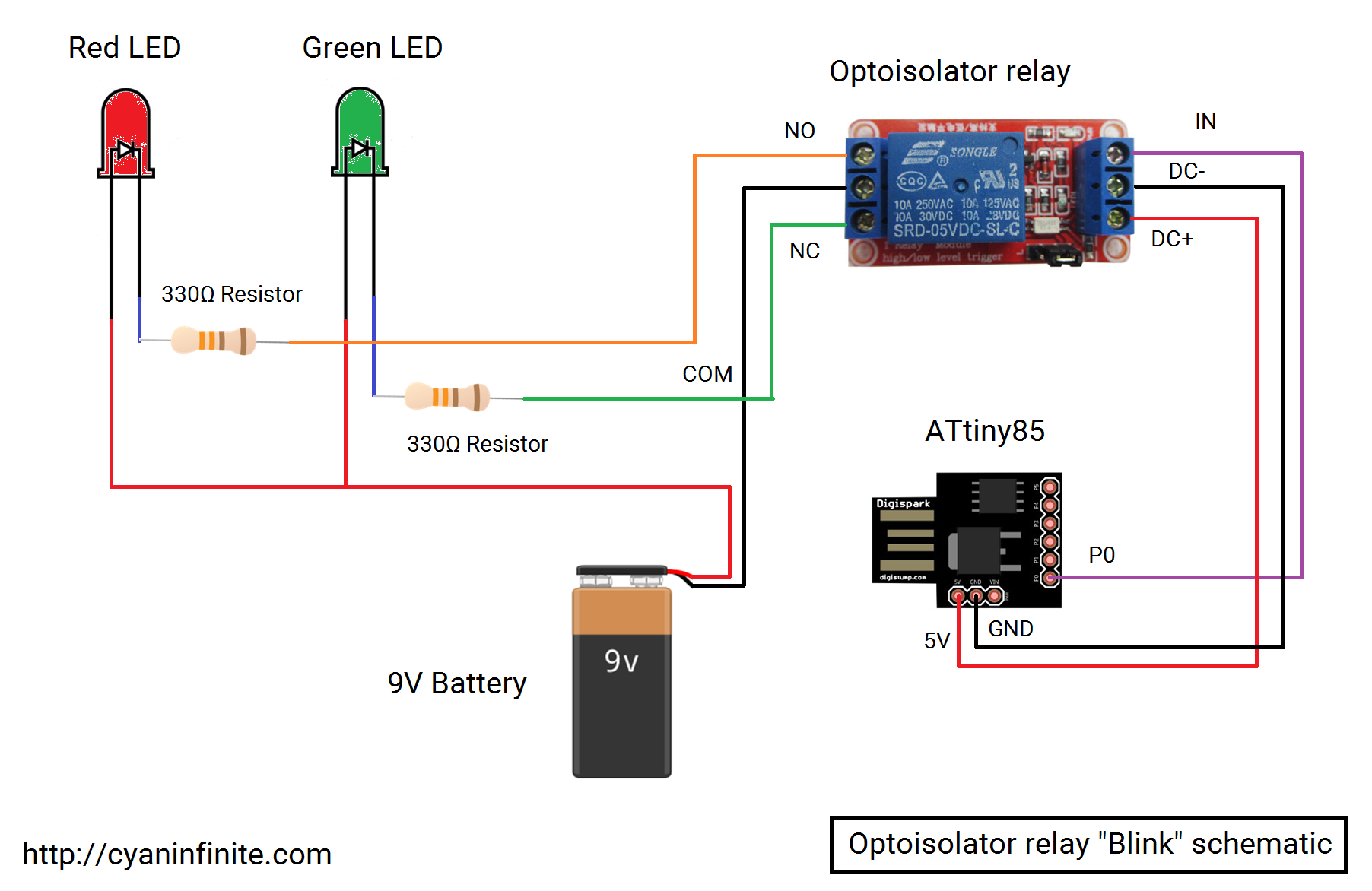
Schematics
Code
The code is actually quite simple, you can just adapt it from the Blink sketch from the Arduino IDE. Instead of using the default pin 13, we will be using pin 0 instead.
void setup() {
  // initialize pin 0 as an output.
  pinMode(0, OUTPUT);
}

void loop() {
  int d = 500;
  digitalWrite(0, HIGH);
  delay(d);
  digitalWrite(0, LOW);
  delay(d);
}