

Contents
How would one be better at using the Arduino? The key is practice and applying what you learn! In this post, that would be 3 activities (with sub tasks) that you can try out, and the solutions will be covered after you have attempted the activities. Let’s begin!
Changelog
V1.0 (22/10/20)
- Initial release
V1.1 (25/10/20)
- Added more details for the questions
- Split the sections up
- Updated images, added graphs
V1.2 (27/10/20)
- Updated solutions section
Overview
These activities serves as a quick way to practice prototyping and the concepts with the Arduino, and to learn a few new components and sensors! I have designed the activities with a few objectives in mind, and would be going through it in the solutions section later below.
- For this practice, please use the Arduino Simulator in Tinkercad Circuit to try them out. (If you have the actual components, it would be recommended to use the actual hardware instead of the simulated one.)
- Should take approximately 1 – 2h to complete all the activities, have fun coding!
If stuck or unsure on how to tackle the activity, the
search engineis your good friend.
And now, to the 3 main activities! (The concepts covered and solutions would be posted in the Solutions section, please try out the activities before going through the solutions.)
Activities
Waving RGB Lighting
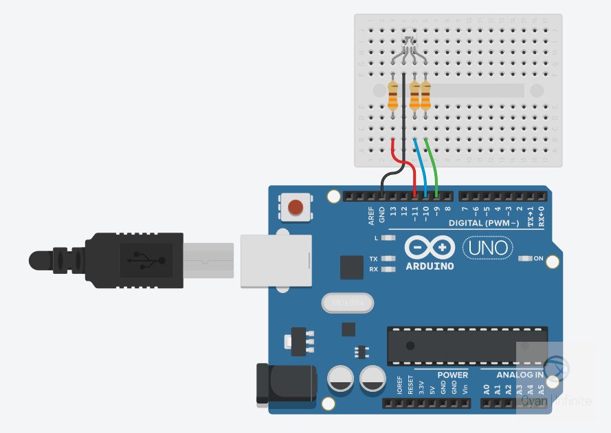
Fascinated with the LED strips on speakers or shopping more? Here’s your chance to create something similar! Let’s try out fading the RGB LED with some sine wave! Wire the schematics as shown.
Components
- RGB LED x 1
- 330 Ohm resistors x 3
- Jumper wires x 4
- Arduino Uno x 1
Task A
Turn On the LEDs one at a time for 2000ms, and then off in the following order: Red, Blue, Green. (It would start from Red again after green.)
Task B
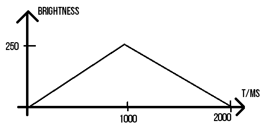
Fade the LEDs in a half triangular waveform for 1000ms and then off using a while loop. It would follow this order: Blue, Red, Green. (It would start from Blue again after Green.)
- Use a
while loopto change the brightness. (Hint: You need 2!) - The maximum brightness would be set at
250. - Each LED would ramp up in brightness for 1s, and then ramp down for 1s. (Total of 2s)
Task C
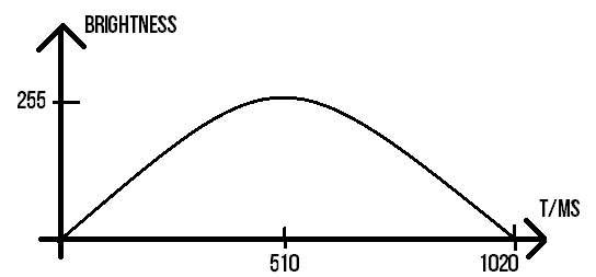
Fade the LEDs in a half cycle sinusoidal waveform for 800ms and then off in the following order: Red, Green, Blue. (It would start from Red again after Blue.)
- Use a
for loopto change the brightness. (Hint: You need 1!) - The maximum brightness would be set at
255. - Each LED would ramp up in brightness for 0.51s, and then ramp down for 0.51s. (Total of 1.02s)
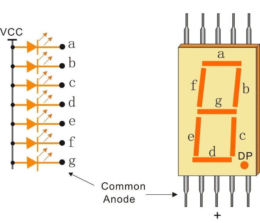
7 Segment Display (Common Anode)
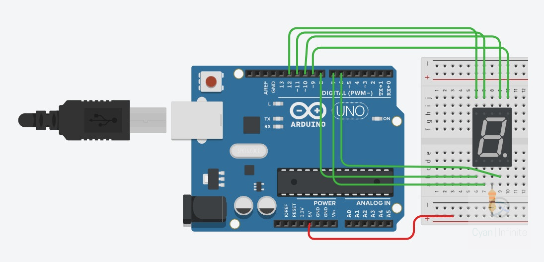
Remember the traffic light digits counting down when we are crossing the road? We would be trying out this common anode 7 segment display, which activates the LED when the pin is grounded! Wire the schematics as shown.
Components
- 7 segment display (Common Anode) x 1
- 330 Ohm resistors x 1
- Jumper wires x 7
- Arduino Uno x 1
Task A
Turn On the segments one at a time for 500ms to test out which pin corresponds to which segments.
- Note down which pins corresponds to which Arduino pin.
Task B
Display the number ‘0’ once. (Hint: Determine which segments need to be ON, which are OFF)
Task C
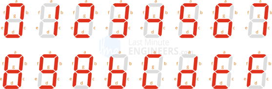
Display the numbers 0 – 9 once.
- You can use a 2D array to store the segments to be ON/OFF to display the different numbers.
for loopcould be used to iterate this 2D array.

Task D
Reverse the order and countdown the number from 9 to 0, after which it would repeat itself. Each number would be displayed for 1 s, just like an actual timer!
Task E
Code for A – F (a hexadecimal extension), and countdown from F to 0.
- Hint: Just add the hexadecimal characters to the 2D array.
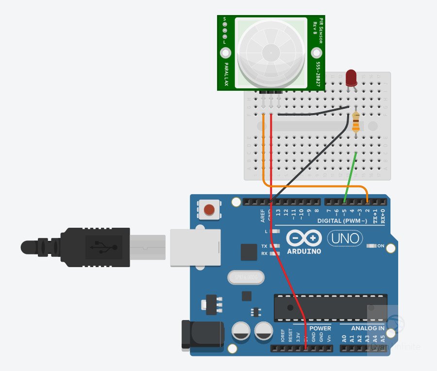
Motion Activated Light (MAL)
In order to save power, some lights in the public area are equipped with a PIR sensor to brighten the area when motion is detected, else it would be dim. For this activity, we would be doing something similar: Turn on the LED for 3 seconds! Wire the schematics as shown.
Components
- PIR Motion Sensor x 1
- LED x 1
- 330 Ohm resistors x 1
- Jumper wires x 5
- Arduino Uno x 1
Task A
Read the values of the PIR Sensor every 0.1s via digitalRead(). Use the Serial monitor to display the PIR sensor value, and determine how long the PIR sensor remains active.
Triggering the sensor
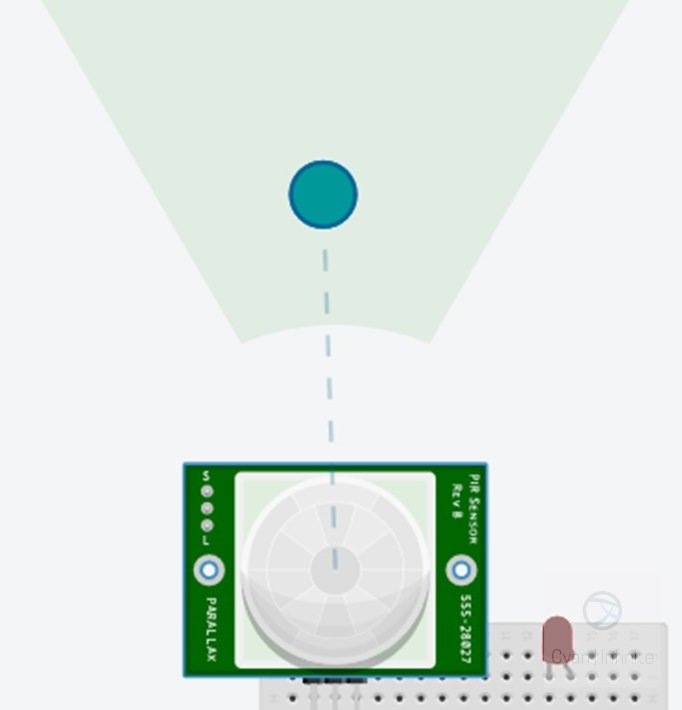
The motion sensor can be triggered by shifting the blue circle when the simulation is running.
Task B
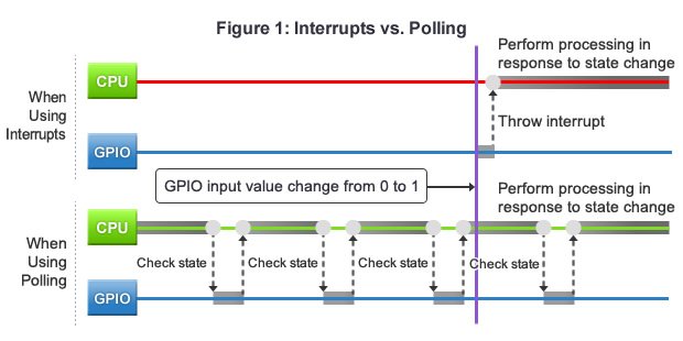
Trigger the LED (using the polling method) to turn on for 3 seconds when motion is detected.
- Recall what is polling.
- Write a function to trigger the LED for 3 seconds when motion is detected.
Task C
Trigger the LED (using the interrupt method) to turn on for 5 seconds when motion is detected.
- Recall what is interrupt, and how is it implemented.
- Write a function (that would be called via the
Interrupt Service Routine, ISR) to update the state of the LED when motion is detected usingattachInterrupt(). delay()andmillis()does not work in the ISR, butmicros()could be used. [5]- Hint: The for loop would be used for keeping track the time, the ISR would be used to set the state of the LED and record the current time with
micros().
Solutions
And the moment you have been waiting for: the solutions! (Note: If you have not attempted the activities and jumped straight here, we strongly advise you to give the activities above a shot beforehand as this is part of the learning process, and you’ll have a greater sense of achievement if you manage to complete it by your own too!)
Waving RGB Lighting
Task A
Concepts
- Usage of Macros via #define to replace values
- Pin initialization in setup() function
- Output signals via digitalWrite()
This is a rather straight forward task of initiallising the GPIO pins as output, and turning on the various LED via the for loop with digitalWrite(PIN, VAL). PIN is the pin to output the “write” signal to, and VAL is the signal value to be outputted.
/*
  Arduino Practice
  > By Cyaninfinite, 1487Quantum ( https://github.com/1487quantum )

  > Activity 1 (RGB LED), Task A
  > Turn each LED color ON & OFF with a time period of 4 seconds. (2s ON, 2s OFF)
*/

#define DELAY 2000          //Define how long to delay LED
const int led_p[3] = {11, 10, 9}; //LED pins to be used: RED BLUE GREEN

void setup()
{
  for (int i = 0; i < 3; ++i) //Pin initialization
    pinMode(led_p[i], OUTPUT);
}

void setLED(int pin) {
  digitalWrite(pin, HIGH);
  delay(DELAY);
  digitalWrite(pin, LOW);
  delay(DELAY);
}

void loop()
{
  for (int i = 0; i < 3; ++i) //Run through the 3 colors
    setLED(led_p[i]);
}
Task B
Concepts
- Using Serial Monitor to track values / debugging
- Using while() loop for iteration
- Output PWM signals via analogWrite()
For this activity, one is constrained to use the while loop to iterate through the brightness with a ramp with a maximum brightness of 250 as shown in the chart below.
So from some quick calculation, one could tell that to reach the brightness of 250 in 1 second, we would iterate 250 times and each iteration of the LED brightness increment should last for 4ms:
4ms x 250 = 1000ms
2 while loops would be used to increment and decrement the LED brightness as described in the runRamp function. After each iteration, we would assign this value to the LED via the analogWrite(PIN, VAL).
/*
  Arduino Practice
  > By Cyaninfinite, 1487Quantum ( https://github.com/1487quantum )

  > Activity 1 (RGB LED), Task B
  > Turn each LED color ON & OFF with a time period of 2 seconds. (1s UP, 1s DOWN)
*/

#define DELAY 4
#define MAX_BRIGHTNESS 250

const int led_p[3] = {10, 11, 9}; //Blue Red Green

void setup()
{
  Serial.begin(115200);        //Setup Serial Monitor, for debugging
  for (int i = 0; i < 3; ++i)
    pinMode(led_p[i], OUTPUT);
}

void runRamp(int pin) {
  int i{0};                       // Index tracker
  while (i < MAX_BRIGHTNESS) { //Ramp Up brightness
       setLED(pin, i);
       ++i;
  }
while (i > 0) {                 //Ramp Down Brightness
    setLED(pin, i);
    --i;
  }
}

void setLED(int pin, int val) {
  analogWrite(pin, val);
  Serial.println(val);    //Print LED Value
  delay(DELAY);
}

void loop()
{
  for (int i = 0; i < 3; ++i)
    runRamp(led_p[i]);
}
Task C
Concepts
- Using for() loop for iteration.
- Figuring out how to achieve the desired function as specified (half-sinewave).
For this activity, one is constrained to use the for loop to iterate through the brightness with a half sinewave with a maximum brightness of 255 as shown in the chart below.
To achieve this waveform, one would be using the first half of the sinewave: the positive cycle. As the entire time period of this wave is 2.04s, we would only be looking at the first 1.02s. With the sine equation 255*sin(θ), we would have to determine the value of theta. (255 is the maximum possible value with the constrains mentioned, hence it would be used as the amplitude.)
- When θ = 0 or π rad, sin(θ) = 0.
- When θ = π/2 rad, sin(θ) = 1. (At maximum)
So as seen above, we have to somehow insert the constrains into the sine equation. Let’s insert the time period (define it as t) into the equation:
Let θ = t*π;
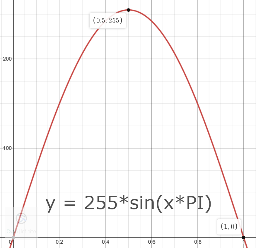
This would not work out, as the theta value is not nomarlised or relative to anything, which does not correspond to our constrains. Lets tweak the equation abit by normalising it with the maximum brightness, 255:
Let θ = (t/255)*π;
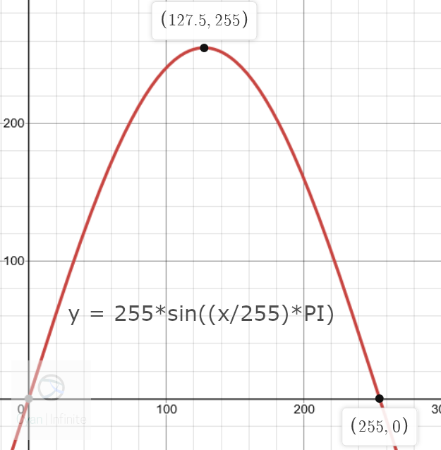
This would make more sense, but the time period is off by a factor of 4! To expand the sinewave by a factor of 4, we could mulitply 1/4 or 0.25 in theta to “stretch” the graph:
Let θ = 0.25*(t/255)*π;

And with this, the function looks similar to the constrain given! Therefore, the final equation would be y = 255*sin(0.25*(t/255)*π), where y is the output value. Only 1 for loop would be needed as the sine function covers both the rising and falling value of the LED.
/*
  Arduino Practice
  > By Cyaninfinite, 1487Quantum ( https://github.com/1487quantum )

  > Activity 1 (RGB LED), Task C
  > Turn each LED color ON & OFF with a time period of 1.02 seconds. (0.51s UP, 0.51s DOWN)
*/

#define DELAY 1
#define PI 3.1415927
#define MAX_BRIGHTNESS 255
#define T_PERIOD 1020


const int led_p[3] = {11, 9, 10}; //Red Green Blue

void setup()
{
  Serial.begin(115200);
  for (int i = 0; i < 3; ++i)
    pinMode(led_p[i], OUTPUT);
}

void runRamp(int pin) {
  for(int i=0; i<T_PERIOD; ++i)
    setLED(pin, i);
}

void setLED(int pin, int val) {
  int x_wave = (int) MAX_BRIGHTNESS*sin(0.25*val/(1.0*MAX_BRIGHTNESS)*PI);
  analogWrite(pin, x_wave);
  Serial.println(x_wave);
  delay(DELAY);
}

void loop()
{
  for (int i = 0; i < 3; ++i)
    runRamp(led_p[i]);
}
7 Segment Display (Common Anode)
Task A
Concepts
- Determine which pins corresponds to which segement via trial and error
- Common Anode 7 segment display uses an inverted logic (1/HIGH would turn OFF the segement, 0/LOW would turn ON the segment.)
/*
  Arduino Practice
  > By Cyaninfinite, 1487Quantum ( https://github.com/1487quantum )

  > Activity 2 (7 segment display, common Anode), Task A
  > =====================================================
  > The common Anode 7 segment display uses a inverted logic: A LOW would turn on the segment,
  > whereas HIGH would turn it off. This task would be used to determine which pin corresponds
  > to which segment.
*/

void setup()
{
  for(int i=6; i<13; ++i){
    pinMode(i, OUTPUT);
    digitalWrite(i, HIGH);	//Turn off all the segment
  }
}

void loop()
{
  for(int i=6; i<13; ++i){
  digitalWrite(i, LOW);		//Turn on segment
  delay(500);
  digitalWrite(i, HIGH);	//Turn off segment
  delay(500);
  }
}
Task B
Concepts
- Using the table of digits to determine how to display the number ‘0’.
- Running the function once: could be done so by placing the function in the setup() function.
/*
  Arduino Practice
  > By Cyaninfinite, 1487Quantum ( https://github.com/1487quantum )

 > Activity 2 (7 segment display, common Anode), Task B
  > =====================================================
  > Display the number 0 on the 7 segment display.
*/

void setup()
{
  for(int i=6; i<13; ++i){
    pinMode(i, OUTPUT);
    digitalWrite(i, LOW);	//Turn on all the segment
  }
  digitalWrite(12, HIGH);	//Turn off segment g to display zero
}

void loop(){}
Task C
Concepts
- Usage of 2D integer arrays to store the various segments to be ON/OFF
- Finding the corresponding segments to display the respective numbers
- Usage of iterators (such as for loop) to run through the segments to be ON/OFF
- Creating a function to display the number on the 7 segment display.
- Display all the numbers only once, not repeat
/*
  Arduino Practice
  > By Cyaninfinite, 1487Quantum ( https://github.com/1487quantum )

  > Activity 2 (7 segment display, common Anode), Task C
  > =====================================================
  > Display the number 0 to 9 once on the 7 segment display.
*/

//Segment pins to turn off for the various numbers
const int dispNum[10][5] = {
  {12},				//Num 0: g
  {10,11,12,8,7},	//Num 1:a f g e d
  {11,6},			//Num 2:f c
  {11,8},			//Num 3:f e
  {10,8,7},			//Num 4:a e d
  {9,8},			//Num 5:b e
  {9,5},			//Num 6:b
  {11,12,8,7},		//Num 7:f g e d
  {0},				//Num 8:-NONE-
  {8}				//Num 9:e
};

void onAllSegments(){
 for(int i=6; i<13; ++i)
    digitalWrite(i, LOW);	//Turn on all the segment
}

void setNum(int num){
  onAllSegments();
  for(int j=0; j<5; ++j){
    //Serial.println(dispNum[num][j]);
    if(dispNum[num][j]==0)
      break;
    else{
      digitalWrite(dispNum[num][j], HIGH);	//Turn off segments
    }
  }
  delay(1000);
}

void setup()
{
  Serial.begin(115200);
  for(int i=6; i<13; ++i){
    pinMode(i, OUTPUT);
    digitalWrite(i, HIGH);	//Turn off all the segement
  }
  //Display 0 - 9
  for(int k=0; k<10; ++k){
    setNum(k);
  }
}

void loop(){}
Task D
Concepts
- Porting the code from the previous activity to display the countdown forever instead of only once.
- Flipping the order of the number display
- Creating a function to display the number on the 7 segment display.
/*
  Arduino Practice
  > By Cyaninfinite, 1487Quantum ( https://github.com/1487quantum )

  > Activity 2 (7 segment display, common Anode), Task D
  > =====================================================
  > Display countdown of the numbers 9 to 0 on the 7 segment display.
*/

//Segment pins to turn off for the various numbers
const int dispNum[10][5] = {
  {12},				//Num 0: g
  {10,11,12,8,7},	//Num 1:a f g e d
  {11,6},			//Num 2:f c
  {11,8},			//Num 3:f e
  {10,8,7},			//Num 4:a e d
  {9,8},			//Num 5:b e
  {9,5},			//Num 6:b
  {11,12,8,7},		//Num 7:f g e d
  {0},				//Num 8:-NONE-
  {8}				//Num 9:e
};

void onAllSegments(){
 for(int i=6; i<13; ++i)
    digitalWrite(i, LOW);	//Turn on all the segment
}

void setNum(int num){
  onAllSegments();
  for(int j=0; j<5; ++j){
    Serial.println(dispNum[num][j]);
    if(dispNum[num][j]==0)
      break;
    else{
      digitalWrite(dispNum[num][j], HIGH);	//Turn off segments
    }
  }
  delay(1000);
}

void setup()
{
  Serial.begin(115200);
  for(int i=6; i<13; ++i){
pinMode(i, OUTPUT);
digitalWrite(i, HIGH); //Turn off all the segment
} }

void loop(){ //Display 9 - 0
for(int k=9; k>=0; --k){
    setNum(k);
  }
}
Task E
Concepts
- Appending to the 2D integer array to display the hexadeciamal extension of the countdown.
- Modifying the iterator (for loop) to account for the extension.
/*
  Arduino Practice
  > By Cyaninfinite, 1487Quantum ( https://github.com/1487quantum )

  > Activity 2 (7 segment display, common Anode), Task E
  > =====================================================
  > Display countdown of the hexadecimal numbers F to 0 on the 7 segment display.
*/

//Segment pins to turn off for the various numbers
const int dispNum[10][5] = {
  {12},				//Num 0: g
  {10,11,12,8,7},	//Num 1:a f g e d
  {11,6},			//Num 2:f c
  {11,8},			//Num 3:f e
  {10,8,7},			//Num 4:a e d
  {9,8},			//Num 5:b e
  {9,5},			//Num 6:b
  {11,12,8,7},		//Num 7:f g e d
  {0},				//Num 8:-NONE-
  {8},				//Num 9:e
  {7},				//Num A:d
  {10,9},			//Num B:a b
  {9,12,6},			//Num C:b g c
  {10,11},			//Num D:a f
  {9,6},			//Num E:b c
  {9,6,7}			//Num F:b c d
};

void onAllSegments(){
 for(int i=6; i<13; ++i)
    digitalWrite(i, LOW);	//Turn on all the segment
}

void setNum(int num){
  onAllSegments();
  for(int j=0; j<5; ++j){
    Serial.println(dispNum[num][j]);
    if(dispNum[num][j]==0)
      break;
    else{
      digitalWrite(dispNum[num][j], HIGH);	//Turn off segments
    }
  }
  delay(1000);
}

void setup()
{
  Serial.begin(115200);
  for(int i=6; i<13; ++i){ pinMode(i, OUTPUT); digitalWrite(i, HIGH); //Turn off all the segment } } void loop(){ //Display F - 0 for(int k=15; k>=0; --k){
    setNum(k);
  }
}
Motion Activated Light (MAL)
Task A
Concepts
- Reading digital signals via digitalRead()
/*
  Arduino Practice
  > By Cyaninfinite, 1487Quantum ( https://github.com/1487quantum )

  > Activity 3 (PIR Motion Sensor with LED), Task A
  > =====================================================
  > Read the value of the PIR Motion sensor.
*/

#define PIR_PIN 2

void setup()
{
  pinMode(PIR_PIN, INPUT);
  Serial.begin(115200);
}

int pRead=0;

void loop()
{
  pRead = digitalRead(PIR_PIN);
  Serial.println(pRead);
  delay(100);
}
Task B
Concepts
- Usage of function to enable the LED to be delayed for 3s.
- Reading the PIR Motion Sensor Values via the Polling method.
/*
  Arduino Practice
  > By Cyaninfinite, 1487Quantum ( https://github.com/1487quantum )

  > Activity 3 (PIR Motion Sensor with LED), Task B
  > =====================================================
  > Trigger the LED ON for 3s when motion is detected via polling method.
*/

#define PIR_PIN 2
#define LED_PIN 5

int pRead=0;

void setup()
{
  pinMode(LED_PIN, OUTPUT);
  pinMode(PIR_PIN, INPUT);
}

void turnOnLED(){
  digitalWrite(LED_PIN,HIGH);
  delay(3000);
  digitalWrite(LED_PIN,LOW);
  delay(1);
}


void loop()
{
  pRead = digitalRead(PIR_PIN);
  if(pRead)
    turnOnLED();
  delay(100);
}
Task C
Concepts
- Usage of Interrupts to trigger the LED delay function with a RISING EDGE trigger.
- Usage of micros() to keep track of the timing. (The duration to keep the LED ON after the interrupt has been triggered)
- Creation of interrupt function to be excecuted when the interrupt is triggered.
- Use of volatile variables such that the variables can be accessed in the Interrupt Service Routine (ISR).
/*
  Arduino Practice
  > By Cyaninfinite, 1487Quantum ( https://github.com/1487quantum )

  > Activity 3 (PIR Motion Sensor with LED), Task C
  > =====================================================
  > Trigger the LED ON for 3s when motion is detected via interrupt method.
*/

#define latch_t 3000000

const byte PIR_PIN = 2;
const byte LED_PIN = 5;
volatile byte state = LOW;
volatile unsigned long duration;

void turnOnLED(){
  state = HIGH;
  duration = micros();
}

void setup()
{
  Serial.begin(9600);
  pinMode(LED_PIN, OUTPUT);
  pinMode(PIR_PIN, INPUT);
  attachInterrupt(digitalPinToInterrupt(PIR_PIN), turnOnLED, RISING );
}

void loop()
{
  Serial.println(micros()-duration);
  if(state && micros()-duration<=latch_t){
    digitalWrite(LED_PIN,HIGH);
  }else{
    state = LOW;
    digitalWrite(LED_PIN,LOW);
  }
}
Conclusion
This marks the end of this Arduino practice (or Revision), hopefully this activities were a fun and interesting way to learn various new sensors or components, and a way to figure out how to seek answers online when in doubt. All the best for your future endeavours in prototyping and projects with arduino!
References
- [1] https://www.sunfounder.com/media/wysiwyg/swatches/super-kit-v2-for-Arduino/10_7_seg_display/anode.jpg
- [2] http://gadgetronicx.com/wp-content/uploads/2014/07/7seg1.gif
- [3] https://lastminuteengineers.com/wp-content/uploads/2018/06/7-Segment-Display-Number-Formation-Segment-Contol.png
- [4] https://luytsm.github.io/mcu-cursus/slides/img/polling_vs_interrupts.jpg
- [5] https://arduino.stackexchange.com/questions/22212/using-millis-and-micros-inside-an-interrupt-routine
