Contents
After much consideration, I think I will try to make a self balancing robot first before a ball balancing robot as to get a better understanding of “balancing” algorithms first. Hence, I’m working on a self balancing robot now instead. Actually I had finished a few stuff a few weeks before I wrote this post, so I will be writing Update #2 and Update #3 together.
#Update 2 – 17/10/15:
Don’t really have any pictures on it, majority of the time was spend testing parts only. I decided to build a self balancing robot first to get more understanding on how balancing robot work. This is because 2 wheel self balancing robot only have to handle 1 axis (the x-axis), whereas the ball balancing robot have to handle 3 axis, which is more complicated.
Micro-controller
- Using a Arduino Uno for testing purposes, intending to get a smaller micro controller soon
- Thought about using ATtiny85, but it is too small in memory size & slow in terms of speed.
- Verdict: Stick to Arduino Uno for now.
Locomotion (Settled)
- Thought of using the 5V stepper motors for locomotion, but after testing them out, I realised it was way to slow to respond to changes……
- Verdict: Nah, too slow. Will be choosing another type of motor to use.
- Tried out 5V mini rotational servo motors with an Arduino Uno, seems to be a better candidate for the robot
- Verdict: Should be good (enough?). Most likely using 2 FITEC Continuous Servo Motor (FS90R)
- Things to keep in mind while using rotational motors:
- 0° – No movement
- 90° – Clockwise movement (max. speed)
- 180° – Anti-clockwise movement (max. speed)
Sensor
- Interfaced the MPU6050 (Accelerometer & Gyroscope Sensor) with the Arduino Uno, used it to control the speed & direction (aka velocity) of the servos
- When the sensor falls in one direction, the servo has to react in the opposite direction. (~Newton’s 3rd law)
- E.g. If the robot is falling to the left, the servo has to move to the right as to mitigate the fall
Coding
- Implemented a simple program to do crude correction of the falling sensor.
- Will be using only the gyroscope x-axis for now, with the values mapped.
- The velocity of the servo will be determined by adding 90 with how much change there is in the Gyro-sensor (X-axis). (Since at 90, the servo will not be moving.)
#include <Servo.h>
#include <Wire.h>

//MPU
const int MPU=0x68;  // I2C address of the MPU-6050
int16_t AcX,AcY,AcZ,Tmp,GyX,GyY,GyZ;

//Servos
Servo myservoL;  //Left Servo (D10)
Servo myservoR;  //Right Servo (D9)

//Angles
int valL=90;
int valR=90;

void setup()
{
  myservoL.attach(4);  // Left
  myservoR.attach(5);  // Right

  //Initialise Serial at 115200 baud rate
  Serial.begin(115200);

  // Initialize MPU
  Wire.beginTransmission(MPU);
  Wire.write(0x6B);  // PWR_MGMT_1 register
  Wire.write(0);     // set to zero (wakes up the MPU-6050)
  Wire.endTransmission(true);
}

void loop() {

  //val = Serial.parseInt();            // reads the value of the potentiometer (value between 0 and 1023)
  readVal();
  valL=90-map(GyX,-380,30000,0,180);
  valR=90+map(GyX,-380,30000,0,180);
  // sets the servo position according to sensor
  myservoL.write(valL);
   myservoR.write(valR);

  Serial.print(GyX);
  Serial.print("t");
  Serial.print(GyY);
  Serial.print("t");
  Serial.print(GyZ);
  Serial.print("n");
  delay(15);                           // waits for the servo to get there

}

void readVal(){
  Wire.beginTransmission(MPU);
  Wire.write(0x3B);  // starting with register 0x3B (ACCEL_XOUT_H)
  Wire.endTransmission(true);
  Wire.requestFrom(MPU,14,true);  // request a total of 14 registers
  AcX=Wire.read()<<8|Wire.read();  // 0x3B (ACCEL_XOUT_H) & 0x3C (ACCEL_XOUT_L)
  AcY=Wire.read()<<8|Wire.read();  // 0x3D (ACCEL_YOUT_H) & 0x3E (ACCEL_YOUT_L)
  AcZ=Wire.read()<<8|Wire.read();  // 0x3F (ACCEL_ZOUT_H) & 0x40 (ACCEL_ZOUT_L)
  Tmp=Wire.read()<<8|Wire.read();  // 0x41 (TEMP_OUT_H) & 0x42 (TEMP_OUT_L)
  GyX=Wire.read()<<8|Wire.read();  // 0x43 (GYRO_XOUT_H) & 0x44 (GYRO_XOUT_L)
  GyY=Wire.read()<<8|Wire.read();  // 0x45 (GYRO_YOUT_H) & 0x46 (GYRO_YOUT_L)
  GyZ=Wire.read()<<8|Wire.read();  // 0x47 (GYRO_ZOUT_H) & 0x48 (GYRO_ZOUT_L)

}
That’s it for Update #2. Now, moving on to Update #3…
#Update 3 – 24/10/15:
Micro-controller (Settled)
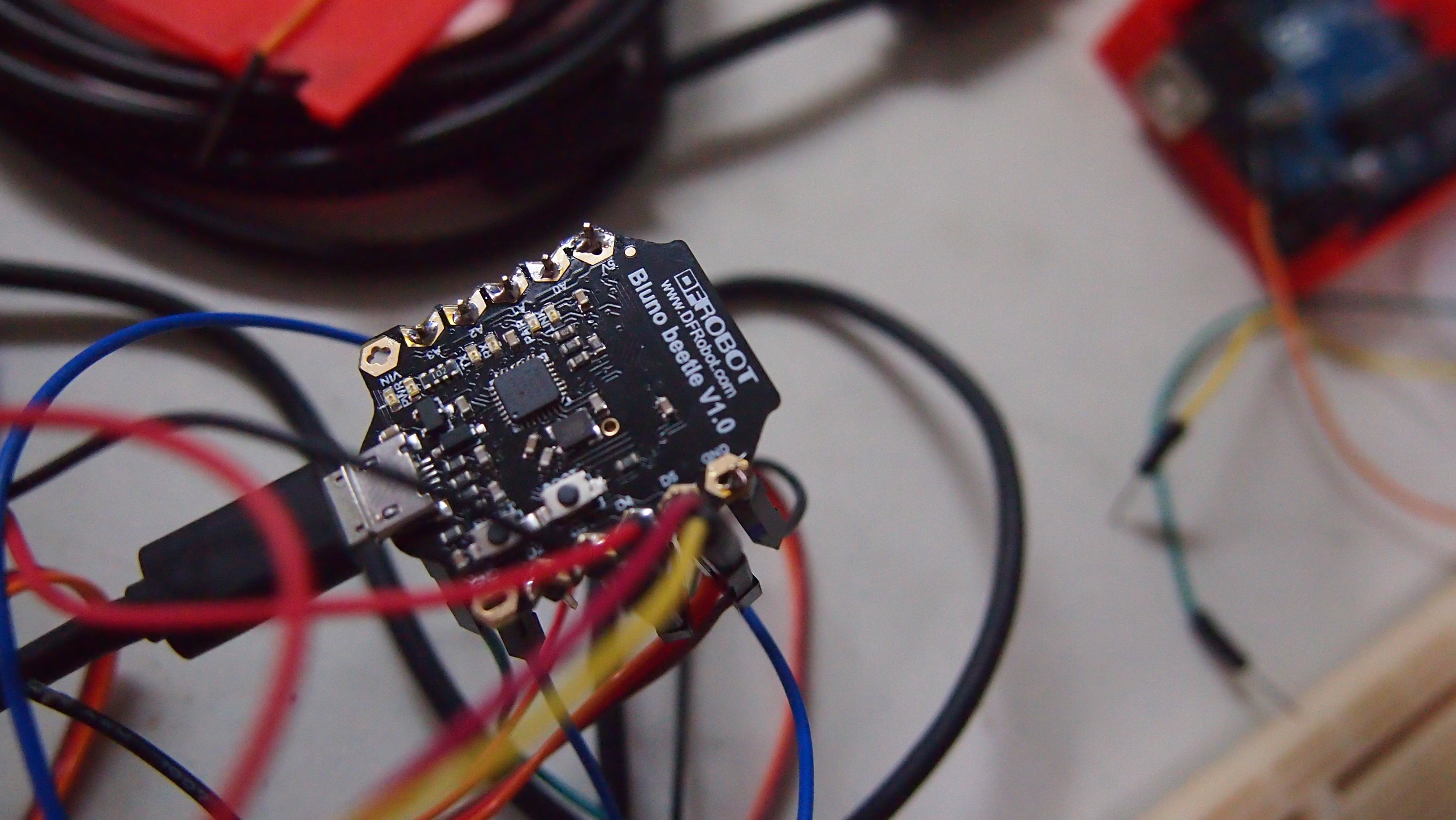
- I think I will be using the Bluno Bettle instead of Arduino Uno
- Features:
- ATmega328@16MHz: Similar to the Arduino Uno
- Bluetooth Low Energy (BT 4.0): Can be used in the future for control
- Micro USB port
- Super Compact Size (28.8mm X 33.1mm, 10g): That’s what I need!
- Working voltage: 5V DC
- Digital Pin x6
- Analog Pin x6
- PWM Output x2
- UART interface x1
- I2C interface x1
- Verdict: Most likely using this micro-controller.
Sensor (Settled)
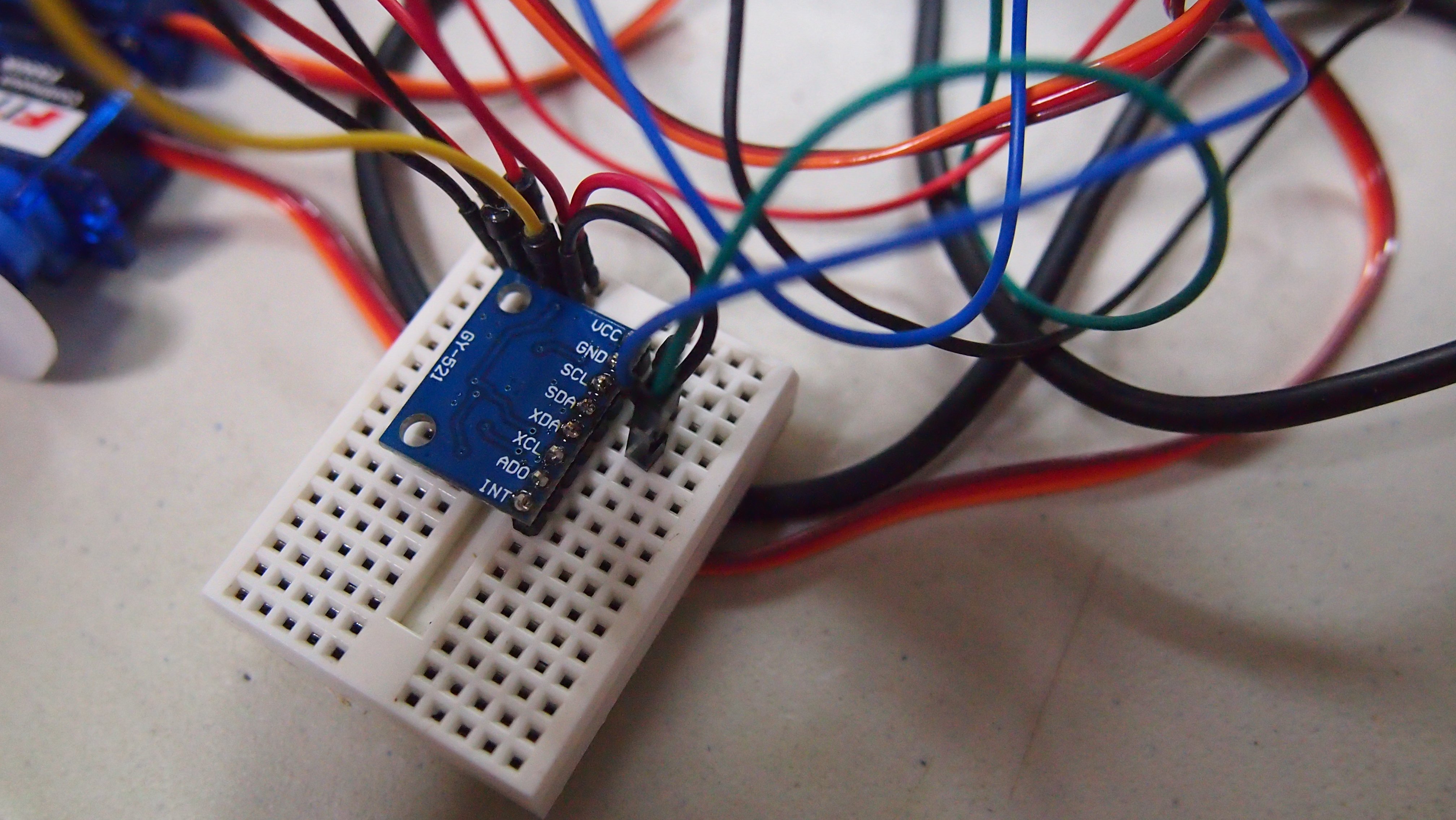
- Interfaced the MPU6050 (Accelerometer & Gyroscope Sensor) with the Bluno Bettle
- Encountered various problems while doing so
- Got -1 for all the output (Gyroscope values), took some steps to resolve problem (in ~2h):
- Changed jumper wires.
- Used I2C Scanner to make sure the Bluno Bettle can detect the MPU6050.
- Did not detect any address at first, so I swapped the wires around. And it detected the sensor. Opps!
Body
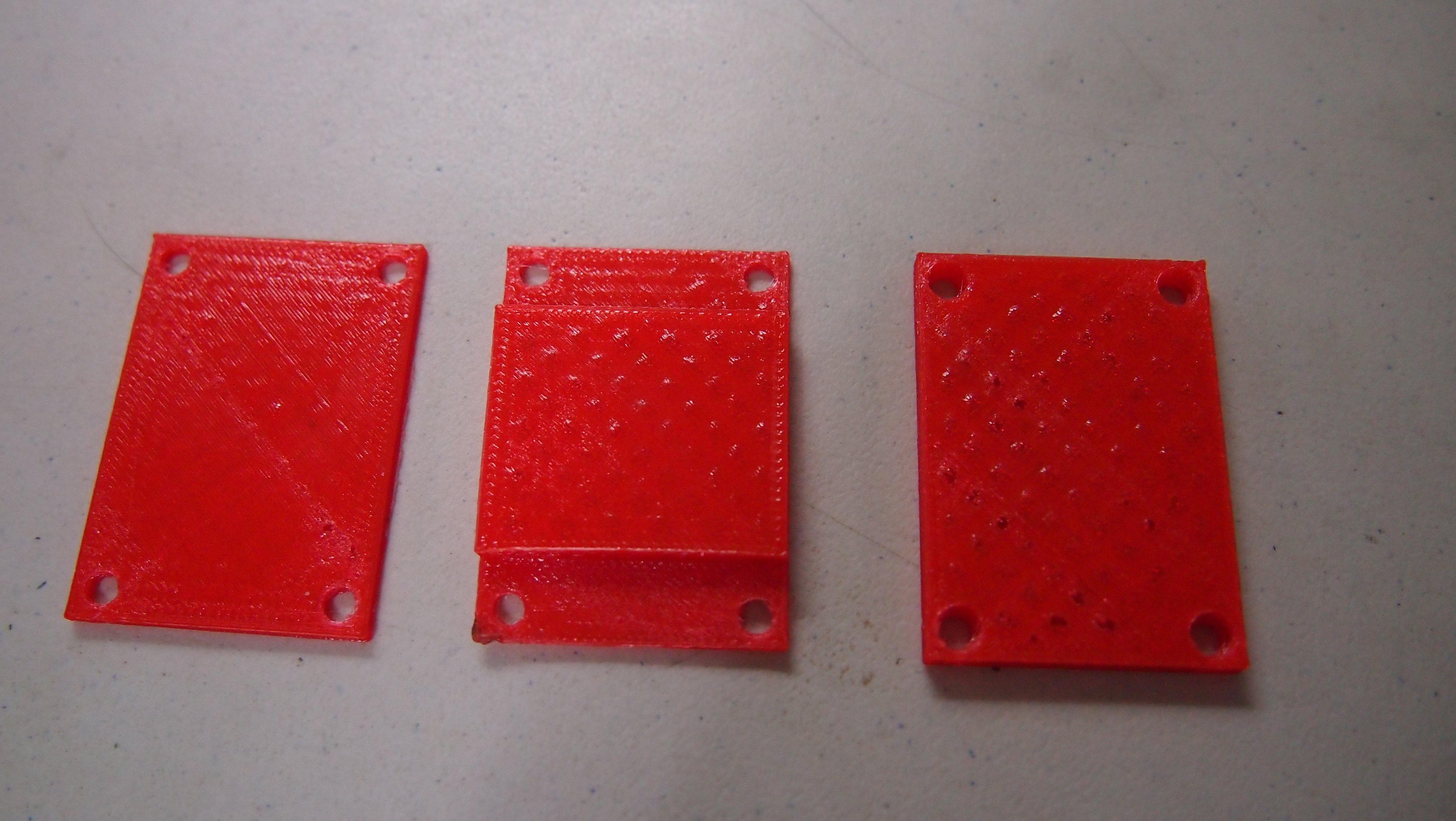
- Designed the body of the robot, it will consist of 3 body plates with stand-offs supporting it.
- I will 3D print the parts, the sketchup file will be uploaded onto Github soon.
- The servos will be attached below, sanwichiched between 2 of the plates.
- The top section of the plate will be where the sensor (MPU6050) & the 5V voltage regulator is. I will be using a 3.7V Lipoly Battery to power the Bluno Bettle.
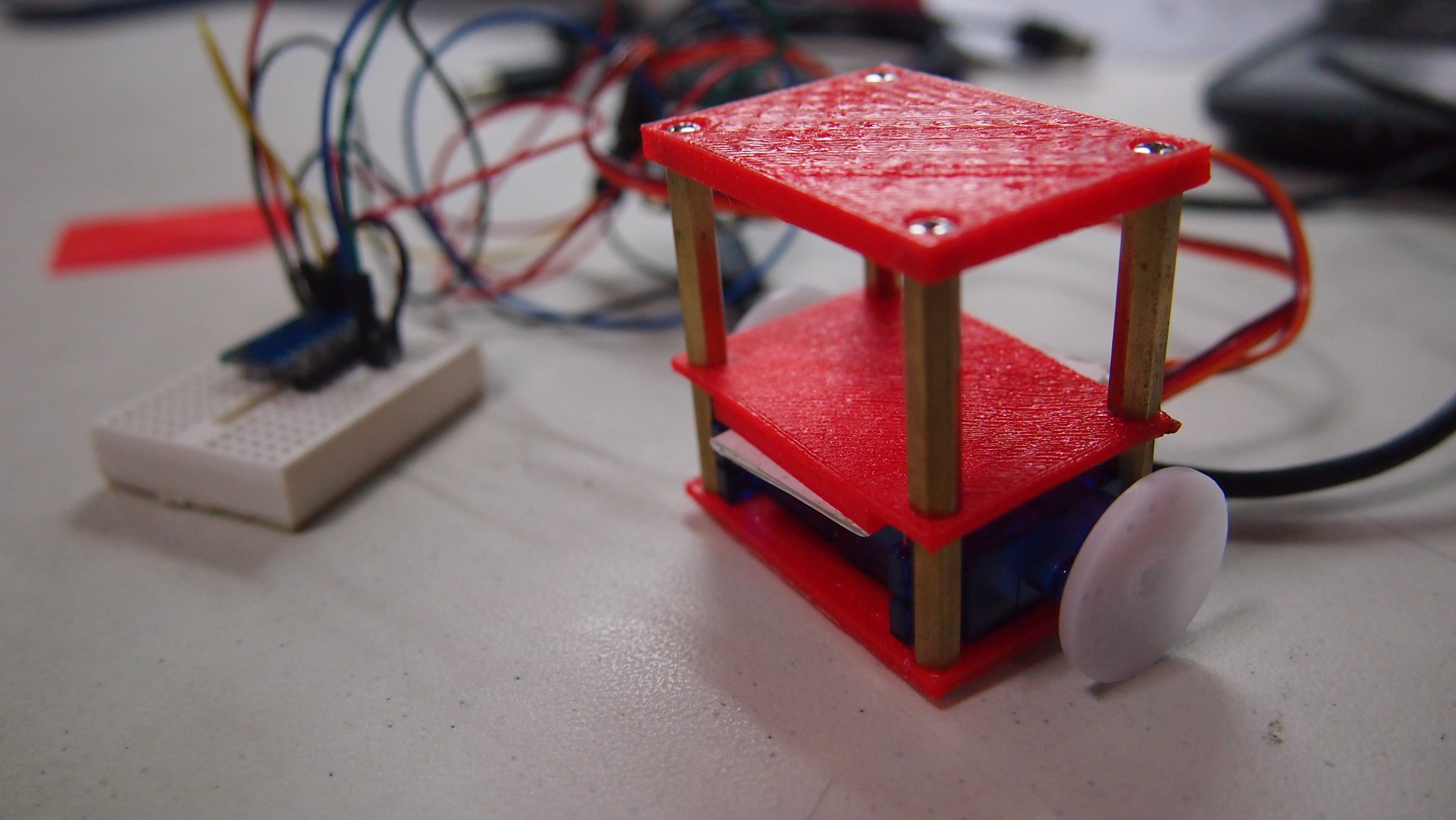
(I think the distance between the top plate & middle plate is a little to small. Maybe I will extend the stand-off by one more the next time.)
Coding:
- Using the same code as previously mentioned. Will be adding the PID filter once I settled everything.
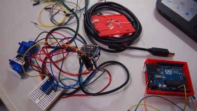
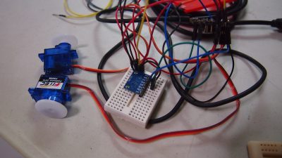
This are a few more other photos that I have taken: (Rather messy setup…)
And that’s about it. This is what I intend to do next time (hopefully):
- Organise the jumper wires nicely (it’s rather messy now).
- Find a good spot to place the Bettle & the battery.
- Modify the body a little bit, maybe 3D print wheels?
- Implement the PID algorithm into the robot.




Hello, I am a student working on a project with a blue-no-beetle. I’ve got a problem. I don’t know which pin I’m going to connect the gyro sensor to. I don’t know where the 12c communication is. I would appreciate it if you could let me know.
Hi jiyeon, there is a I2C contact at the bottom left of the bluno beetle, you can either solder a wire or header onto the contact point. The pinout is as shown below.