
Contents
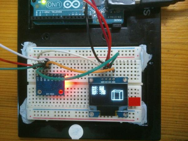
Time to rotate a virtual cube on a 0.96″ OLED Display! In this tutorial, I’ll be using the MPU6050 to get the acceleration values of the X-axis and the Y-Axis, which would then be translated to the speed at which the cube is rotating at. I’ll not be using the values of the gyroscope this time but I may used it in the future.
Overview

For more information on how to use the I2C OLED Display, you can check it out here: Interfacing 0.96″ OLED Display with Arduino UNO
Parts
- Arduino Uno x 1
- MPU6050 (Accelerometer + Gyro Sensor) Module x 1
- 0.96″ I2C OLED Display x 1
- Jumper Wires
What is MPU6050?
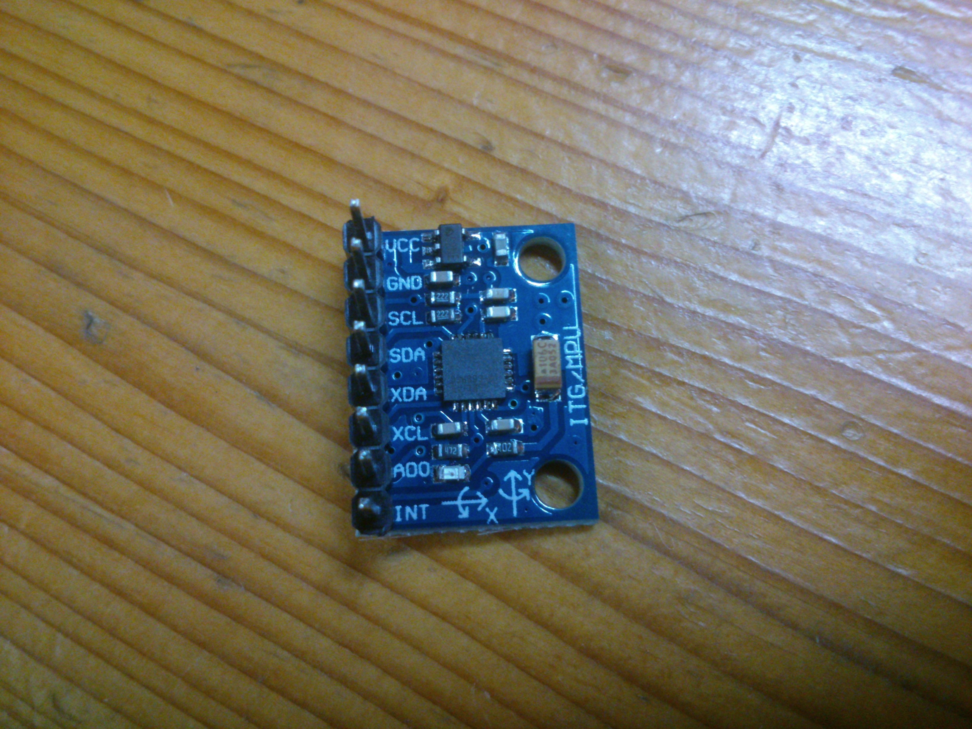
The MPU6050 is a accelerometer and a gyroscope sensor that has the ability to record values on 3 axis (X – Axis, Y – Axis, Z- Axis), and uses I2C bus to interface with the Arduino. This sensor is particular useful in tracking rotational and linear motion of an object at the same time. The advantages of this sensor is that the output for each channel is 16 bits analog to digital conversion hardware , which means that the readings are very accurate, and the fact that this sensor is not expensive too. With all this advantages, many people or hobbyist likes to use the MPU6050 in their projects, which includes self balancing robots, camera stabliser, motion tracking, quadcopters and many more.
Since the accelerometer and the gyroscope are packaged together in the MPU6050, we can take advantage of this to combine the readings of both sensors to get an even more accurate & stable value of the linear and rotational motion of the object.
How does it work?
Well, we would first get raw values of both the x & y channels from the MPU6050 via the I2C bus, which I will map the raw values of both the x-axis & y-axis channels from -17000 <-> 17000 to -50 <-> 50. This value is then used to determine the speed at which the cube is rotating at. When the mapped value of the x-axis is positive, the cube will rotate to the right, vice versa. When the mapped value of the y-axis is positive, the cube will rotate upwards, vice versa. We can make the cube rotate diagonally when the sensor is tilted sideways.
I’ll be display the raw values of both x-axis and y-axis channels of the accelerometer and gyroscope on the left side of the screen for debugging purposes, even though I’m not using the values of the gyroscope yet. I might use it in the future to further increase the accuracy of the readings of motion.
A great thanks to Adafruit for their graphic library, mike rankin for his rotating 3D cube part of the code.
Demo
Code
/*
 Draws a 3d rotating cube on the freetronics OLED screen.
 Original code was found at http://forum.freetronics.com/viewtopic.php?f=37&t=5495
 Thanks to Adafruit at http://www.adafruit.com for the great display and sensor libraries
 */
#include <SPI.h>
#include <Adafruit_SSD1306.h>
#include <Adafruit_GFX.h>
#include <Wire.h>

//MPU
const int MPU=0x68;  // I2C address of the MPU-6050
int16_t AcX,AcY,AcZ,Tmp,GyX,GyY,GyZ;

//Display
#define OLED_RESET 4
Adafruit_SSD1306 display(OLED_RESET);

// OLED I2C bus address
#define OLED_address  0x3c

float xx,xy,xz;
float yx,yy,yz;
float zx,zy,zz;

float fact;

int Xan,Yan;

int Xoff;
int Yoff;
int Zoff;

struct Point3d
{
  int x;
  int y;
  int z;
};

struct Point2d
{
  int x;
  int y;
};


int LinestoRender; // lines to render.
int OldLinestoRender; // lines to render just in case it changes. this makes sure the old lines all get erased.

struct Line3d
{
  Point3d p0;
  Point3d p1;
};

struct Line2d
{
  Point2d p0;
  Point2d p1;
};

Line3d Lines[12];  //Number of lines to render
Line2d Render[12];
Line2d ORender[12];

/***********************************************************************************************************************************/
// Sets the global vars for the 3d transform. Any points sent through "process" will be transformed using these figures.
// only needs to be called if Xan or Yan are changed.
void SetVars(void)
{
  float Xan2,Yan2,Zan2;
  float s1,s2,s3,c1,c2,c3;

  Xan2 = Xan / fact; // convert degrees to radians.
  Yan2 = Yan / fact;

  // Zan is assumed to be zero

  s1 = sin(Yan2);
  s2 = sin(Xan2);

  c1 = cos(Yan2);
  c2 = cos(Xan2);

  xx = c1;
  xy = 0;
  xz = -s1;

  yx = (s1 * s2);
  yy = c2;
  yz = (c1 * s2);

  zx = (s1 * c2);
  zy = -s2;
  zz = (c1 * c2);
}


/***********************************************************************************************************************************/
// processes x1,y1,z1 and returns rx1,ry1 transformed by the variables set in SetVars()
// fairly heavy on floating point here.
// uses a bunch of global vars. Could be rewritten with a struct but not worth the effort.
void ProcessLine(struct Line2d *ret,struct Line3d vec)
{
  float zvt1;
  int xv1,yv1,zv1;

  float zvt2;
  int xv2,yv2,zv2;

  int rx1,ry1;
  int rx2,ry2;

  int x1;
  int y1;
  int z1;

  int x2;
  int y2;
  int z2;

  int Ok;

  x1=vec.p0.x;
  y1=vec.p0.y;
  z1=vec.p0.z;

  x2=vec.p1.x;
  y2=vec.p1.y;
  z2=vec.p1.z;

  Ok=0; // defaults to not OK

  xv1 = (x1 * xx) + (y1 * xy) + (z1 * xz);
  yv1 = (x1 * yx) + (y1 * yy) + (z1 * yz);
  zv1 = (x1 * zx) + (y1 * zy) + (z1 * zz);

  zvt1 = zv1 - Zoff;


  if( zvt1 < -5){
    rx1 = 256 * (xv1 / zvt1) + Xoff;
    ry1 = 256 * (yv1 / zvt1) + Yoff;
    Ok=1; // ok we are alright for point 1.
  }


  xv2 = (x2 * xx) + (y2 * xy) + (z2 * xz);
  yv2 = (x2 * yx) + (y2 * yy) + (z2 * yz);
  zv2 = (x2 * zx) + (y2 * zy) + (z2 * zz);

  zvt2 = zv2 - Zoff;


  if( zvt2 < -5){
    rx2 = 256 * (xv2 / zvt2) + Xoff;
    ry2 = 256 * (yv2 / zvt2) + Yoff;
  } else
  {
    Ok=0;
  }

  if(Ok==1){
  ret->p0.x=rx1;
  ret->p0.y=ry1;

  ret->p1.x=rx2;
  ret->p1.y=ry2;
  }
 // The ifs here are checks for out of bounds. needs a bit more code here to "safe" lines that will be way out of whack, so they dont get drawn and cause screen garbage.

}


/***********************************************************************************************************************************/
void setup() {
 Wire.begin();
  display.begin(SSD1306_SWITCHCAPVCC, 0x3c);  // initialize with the I2C addr 0x3D (for the 128x64)
  display.clearDisplay();   // clears the screen and buffer


Wire.begin();

  fact = 180 / 3.14159265358979323846264338327950; // conversion from degrees to radians.

  Xoff = 90; // positions the center of the 3d conversion space into the center of the OLED screen. This is usally screen_x_size / 2.
  Yoff = 32; // screen_y_size /2
  Zoff = 750;   //Size of cube, larger no. = smaller cube

// line segments to draw a cube. basically p0 to p1. p1 to p2. p2 to p3 so on.

// Front Face.

  Lines[0].p0.x=-50;
  Lines[0].p0.y=-50;
  Lines[0].p0.z=50;
  Lines[0].p1.x=50;
  Lines[0].p1.y=-50;
  Lines[0].p1.z=50;

  Lines[1].p0.x=50;
  Lines[1].p0.y=-50;
  Lines[1].p0.z=50;
  Lines[1].p1.x=50;
  Lines[1].p1.y=50;
  Lines[1].p1.z=50;

  Lines[2].p0.x=50;
  Lines[2].p0.y=50;
  Lines[2].p0.z=50;
  Lines[2].p1.x=-50;
  Lines[2].p1.y=50;
  Lines[2].p1.z=50;

  Lines[3].p0.x=-50;
  Lines[3].p0.y=50;
  Lines[3].p0.z=50;
  Lines[3].p1.x=-50;
  Lines[3].p1.y=-50;
  Lines[3].p1.z=50;


//back face.

  Lines[4].p0.x=-50;
  Lines[4].p0.y=-50;
  Lines[4].p0.z=-50;
  Lines[4].p1.x=50;
  Lines[4].p1.y=-50;
  Lines[4].p1.z=-50;

  Lines[5].p0.x=50;
  Lines[5].p0.y=-50;
  Lines[5].p0.z=-50;
  Lines[5].p1.x=50;
  Lines[5].p1.y=50;
  Lines[5].p1.z=-50;

  Lines[6].p0.x=50;
  Lines[6].p0.y=50;
  Lines[6].p0.z=-50;
  Lines[6].p1.x=-50;
  Lines[6].p1.y=50;
  Lines[6].p1.z=-50;

  Lines[7].p0.x=-50;
  Lines[7].p0.y=50;
  Lines[7].p0.z=-50;
  Lines[7].p1.x=-50;
  Lines[7].p1.y=-50;
  Lines[7].p1.z=-50;

// now the 4 edge lines.

  Lines[8].p0.x=-50;
  Lines[8].p0.y=-50;
  Lines[8].p0.z=50;
  Lines[8].p1.x=-50;
  Lines[8].p1.y=-50;
  Lines[8].p1.z=-50;

  Lines[9].p0.x=50;
  Lines[9].p0.y=-50;
  Lines[9].p0.z=50;
  Lines[9].p1.x=50;
  Lines[9].p1.y=-50;
  Lines[9].p1.z=-50;

  Lines[10].p0.x=-50;
  Lines[10].p0.y=50;
  Lines[10].p0.z=50;
  Lines[10].p1.x=-50;
  Lines[10].p1.y=50;
  Lines[10].p1.z=-50;

  Lines[11].p0.x=50;
  Lines[11].p0.y=50;
  Lines[11].p0.z=50;
  Lines[11].p1.x=50;
  Lines[11].p1.y=50;
  Lines[11].p1.z=-50;

  LinestoRender=12;
  OldLinestoRender=LinestoRender;

  // Initialize MPU
  Wire.beginTransmission(MPU);
  Wire.write(0x6B);  // PWR_MGMT_1 register
  Wire.write(0);     // set to zero (wakes up the MPU-6050)
  Wire.endTransmission(true);

}
/***********************************************************************************************************************************/
void RenderImage( void)
{
  // renders all the lines after erasing the old ones.
  // in here is the only code actually interfacing with the OLED. so if you use a different lib, this is where to change it.

 for (int i=0; i<OldLinestoRender; i++ )
  {
   display.drawLine(ORender[i].p0.x,ORender[i].p0.y,ORender[i].p1.x,ORender[i].p1.y, BLACK); // erase the old lines.
  }


  for (int i=0; i<LinestoRender; i++ )
  {
   display.drawLine(Render[i].p0.x,Render[i].p0.y,Render[i].p1.x,Render[i].p1.y, WHITE);
  }
  OldLinestoRender=LinestoRender;


  Wire.beginTransmission(MPU);
  Wire.write(0x3B);  // starting with register 0x3B (ACCEL_XOUT_H)
  Wire.endTransmission(true);
  Wire.requestFrom(MPU,14,true);  // request a total of 14 registers
  AcX=Wire.read()<<8|Wire.read();  // 0x3B (ACCEL_XOUT_H) & 0x3C (ACCEL_XOUT_L)
  AcY=Wire.read()<<8|Wire.read();  // 0x3D (ACCEL_YOUT_H) & 0x3E (ACCEL_YOUT_L)
  AcZ=Wire.read()<<8|Wire.read();  // 0x3F (ACCEL_ZOUT_H) & 0x40 (ACCEL_ZOUT_L)
  Tmp=Wire.read()<<8|Wire.read();  // 0x41 (TEMP_OUT_H) & 0x42 (TEMP_OUT_L)
  GyX=Wire.read()<<8|Wire.read();  // 0x43 (GYRO_XOUT_H) & 0x44 (GYRO_XOUT_L)
  GyY=Wire.read()<<8|Wire.read();  // 0x45 (GYRO_YOUT_H) & 0x46 (GYRO_YOUT_L)
  GyZ=Wire.read()<<8|Wire.read();  // 0x47 (GYRO_ZOUT_H) & 0x48 (GYRO_ZOUT_L)
  // text display tests
  display.setTextSize(1);
  display.setTextColor(WHITE);
  display.setCursor(0,0);
  //Display ACC
  display.print("AcX: ");
  display.println(AcX);
  display.print("AcY: ");
  display.println(AcY);
  //Display gyro
  display.print("GyX: ");
  display.println(GyX);
  display.print("GyY: ");
  display.println(GyY);
  //delay(10);
}


/***********************************************************************************************************************************/

void loop() {
  display.display();
  display.clearDisplay();   // clears the screen and buffer

 // PIX=GREEN; // colours of all lines drawn will be green until changed.

  //For cube rotation
  int xOut=0;
  int yOut=0;

  xOut = map(AcX,-17000,17000,-50,50);
    yOut = map(AcY,-17000,17000,-50,50);

 Xan+=xOut;
 Yan+=yOut;


  Yan=Yan % 360;
  Xan=Xan % 360; // prevents overflow.


  SetVars(); //sets up the global vars to do the conversion.

  for(int i=0; i<LinestoRender ; i++)
  {
    ORender[i]=Render[i]; // stores the old line segment so we can delete it later.
    ProcessLine(&Render[i],Lines[i]); // converts the 3d line segments to 2d.
  }

  RenderImage(); // go draw it!


}
Nice,
the code needed a tiny bit of tweaking for me to get it to work, but looks great!
Thanks very much for your careful commenting. It really helps understand what each component does and the considerations you applied. Much appreciated.