
Contents
Ever needed a microcontroller that is small for projects with low power consumption, but more powerful than a Arduino Uno? Seeeduino XIAO could be a potential candidate, with a 32Bit microcontroller onboard. Without further ado, let’s take a look at this board!
This microcontroller has been sponsored by the Seeed Studio team, a great shoutout to them!
About Seeed Studio
Seeed Studio is the IoT hardware enabler providing services over 10 years that empower makers to realize their projects and products. Seeed offers a wide array of hardware platforms and sensor modules ready to be integrated with existing IoT platforms, and one-stop PCB fabrication and PCB assembly service. Seeed Studio provides a wide selection of electronic parts including Arduino, Raspberry Pi and many different development board platforms, especially the Grove System to help engineers and makers avoid jumper wires problems. Seeed Studio has developed more than 280 Grove modules covering a wide range of applications that can fulfill a variety of needs.
Specifications
The Seeeduino Xiao is 20mm x 17.5mm small, packing with a 32 Bit ARM® Cortex®-M0+ 48MHz microcontroller (SAMD21G18), that has a SRAM of 32KB & 256KB Flash memory. Below are the specifications of the microcontroller:
| Seeeduino Xiao | |
|---|---|
| CPU | ARM Cortex-M0+ CPU(SAMD21G18) |
| Dimensions | 20×17.5×3.5mm |
| Clock Speed | ~48MHz |
| Flash Memory | 256KB |
| SRAM | 32KB |
| Digital I/O Pins | 11 |
| Analog I/O Pins | 11 |
| I2C interface | 1 |
| SPI interface | 1 |
| UART interface | 1 |
| USB Interface | Type-C |
| Logic Level | 3.3V |
| 🔌 Power | 3.3V/5V DC |
Fun fact: Xiao (小) refers to small in Mandarin!
Packaging
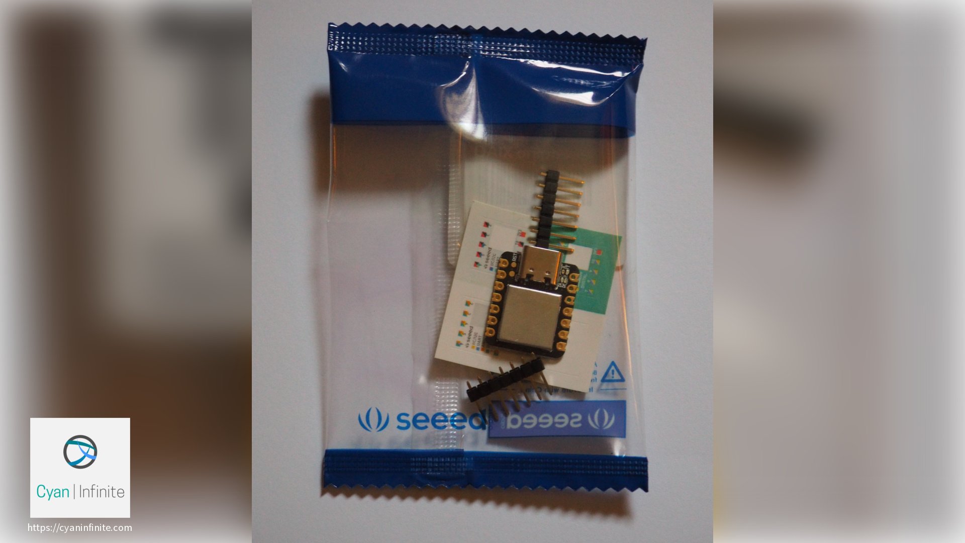
The Seeeduino Xiao is packaged in a clear packaging, though a reusable zip-lock electrostatic packaging would be nice to have. It includes the following components:
- The microcontroller (Seeeduino Xiao)
- Male header pins (7 pins) x 2
- Schematics sticker x 3 + Blank Sticker x 1

The pinout stickers is useful in pointing out which pins corresponds to which “leg”, but the only drawback is that it did not managed to cover all the pins. (Which is actually good enough to get things done.)
However, a Type C data cable is not included in the package, you would have to get one yourself to interface with the Xiao. (Ensure it has data transfer capability, else it would only power the microcontroller without being able to upload anything!)
Fun fact: I decided to use a female-male header instead of the default male header as it seems easier to interface the microcontroller to the various components. The only issue is that it is harder to get the board into the Bootloader mode (by shorting the Reset pins) as the female header is somewhat blocking.
Pinouts
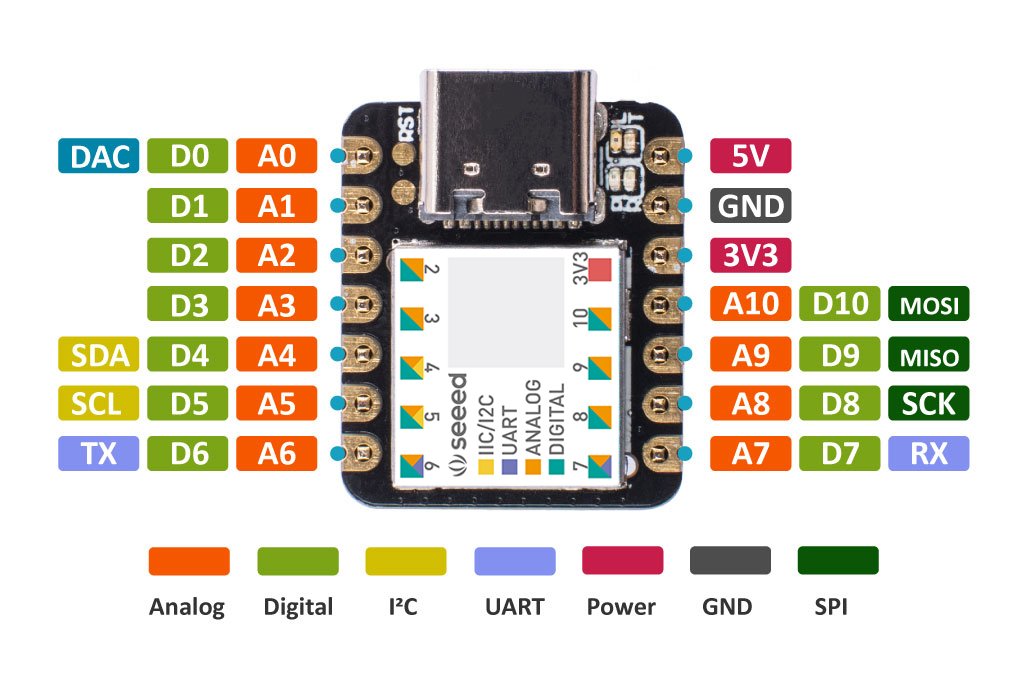
The Xiao has 14 pins, where 11 are GPIO pins (all which can be used as either as a Digital pin or Analog pin). The VIN (Under the board) & 5V pin could be used to power the Xiao with a 5V power supply, as it is connected to a XC6206P3232MR DC-DC Power Converter (5V->3.3V).
Take note that the I/O pins run at 3.3V, similar to the Raspberry Pi or ESP32.
Overview
The table below summarises the functions of the pins:
| Left | Right | ||
|---|---|---|---|
| Pin | Function | Pin | Function |
| 0 | A0 / D0 / DAC / INT_2 | 7 | A7 / D7 / RX / INT_9 |
| 1 | A1 / D1 / INT_4 | 8 | A8 / D8 / SCK / INT_7 |
| 2 | A2 / D2 / INT_10 | 9 | A9 / D9 / MISO / INT_5 |
| 3 | A3 / D3 / INT_11 | 10 | A10 / D10 / MOSI / INT_6 |
| 4 | A4 / D4 / SDA / INT_NMI | 11 | PIO_TIMER_ALT/ INT_3 |
| 5 | A5 / D5 / SCL / INT_9 | 12 | PIO_TIMER/ INT_2 |
| 6 | A6 / D6 / TX / INT_8 | 13 | LED / PIO_PWM / INT_1 |
Note: Pins 11 – 13 could not be accessed via jumper wires, and Pin 13 ties to the onboard LED.
Interrupts
Note: We’ll be using INT_<NUM> to refer to an interrupt. For example, INT_0 refers to Interrupt 0, where the pin could be called via EXTERNAL_INT_0.
All the pins can be used as an interrupt, however pins 5 & 7 cannot be used simultaneously as they are linked to the same name (EXTERNAL_INT_9).
Timers
The timers are located at pin 11 & 12.
Programming
In this tutorial, we’ll be exploring 2 methods in which Xiao could be program with, which are:
We’ll be using a similar code for both section, which pulsates the LED on the Xiao.
You can either go through both sections or skip to the prefered method of programming the Xiao.
Fun fact: The Xiao can also be used as a HID (Human Interface Device) such as a mouse or keyboard, or as a MIDI (Musical Instrument Digital Interface) device, and many more via the TinyUSB Library!
Arduino
In this tutorial, we’ll be looking at how to setup the board with the Arduino IDE on Windows.
Requirements
- Arduino IDE: https://www.arduino.cc/en/Main/Software
- Xiao Microcontroller
- Type C Cable (Connected to the microcontroller)
Installation
We’ll be installing the driver first via the Arduino Board Manager. Open up the Arduino IDE & navigate to the preference settings under File > Preference.
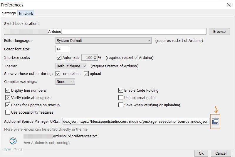
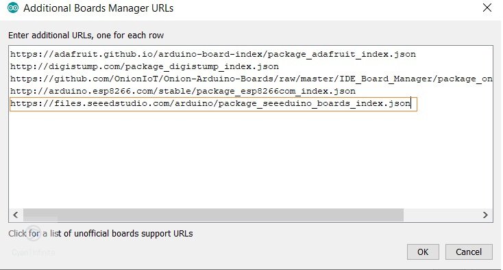
Add the following link to the Boards manager, below the URLs. This would update the device manager list.
https://files.seeedstudio.com/arduino/package_seeeduino_boards_index.json
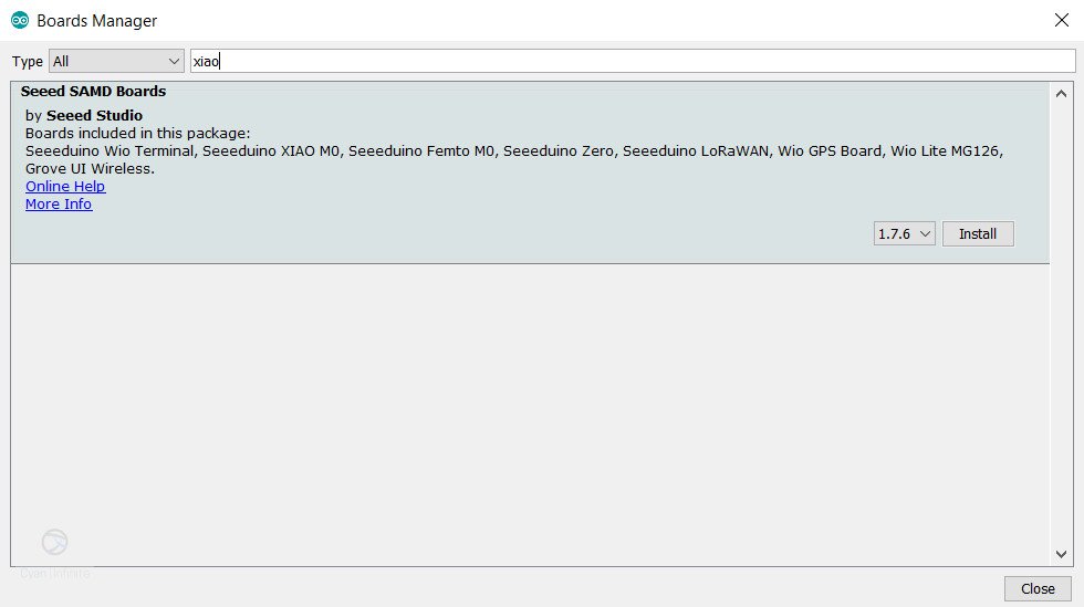
After the URL has been added, proceed to the Boards Manager under Tools > Boards > Boards Manager.... Type Xiao, and install the Seeed SAMD Boards. (At the point of writing, the latest version is 1.7.6) This would install the necessary drivers for the microcontroller.
The installation would take some time depending on your internet connectivity.
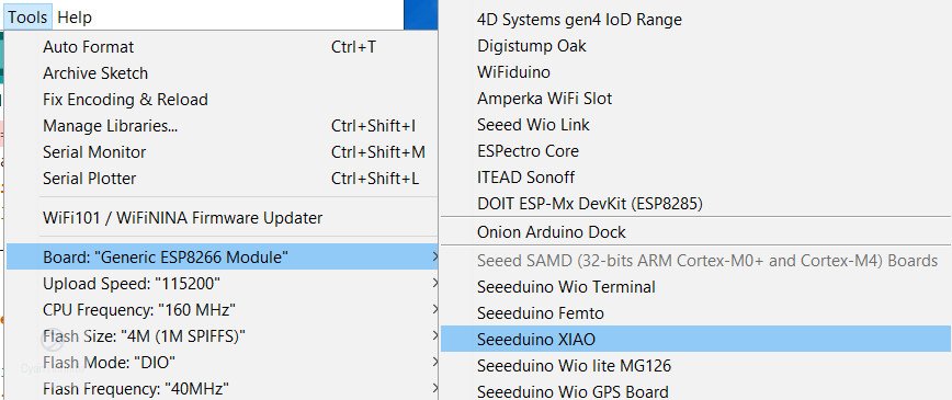
Once the installation is done, we would be selecting the Seeeduino XIAO under Tools > Board. With that, we are ready to use the microcontroller!
Hello, (Pulsating) world!
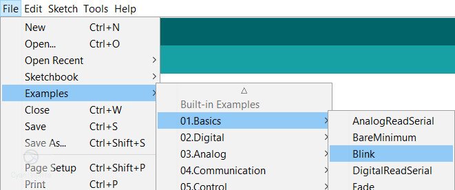
As always, we would be uploading a simple blink program (as for hardware projects with LEDs) to the Xiao to test out the communication between them works. Select the Blink example under File > Examples > 01.Basics > Blink.
We would be adding a little modification to the code: turning it on for 300ms and then off for 1700ms. Edit the code as shown below and upload to the Xiao.
// the setup function runs once when you press reset or power the board
void setup() {
  // initialize digital pin LED_BUILTIN (13) as an output.
  pinMode(LED_BUILTIN, OUTPUT);
}

// the loop function runs over and over again forever
void loop() {
  digitalWrite(LED_BUILTIN, HIGH);   // turn the LED on (HIGH is the voltage level)
  delay(1700);                       // wait
  digitalWrite(LED_BUILTIN, LOW);    // turn the LED off by making the voltage LOW
  delay(300);                       // wait
}
If the Orange LED on the Xiao pulsates, the program has been sucessfully been uploaded. Hooray!
The onboard LED is Active Low, which means the LED only turns on when a LOW or 0 is written.
CircuitPython

CircuitPython is developed by Adafruit, which allows one to program the various micrcontrollers in Python. We’ll be using the Mu Editor to code the Xiao microcontroller in Python.
Note that CircuitPython does not support interrupts currently.
Requirements
- Mu Editor: Used as the Code editor for CircuitPython, which works with CircuitPython boards.
- Xiao Bootloader: Download the bootloader, which is in uf2 format.
- Xiao Microcontroller
- Type C Cable (Connected to the microcontroller)
- Jumper wire x 1: To enter into DFU bootloader mode to upload the python code.
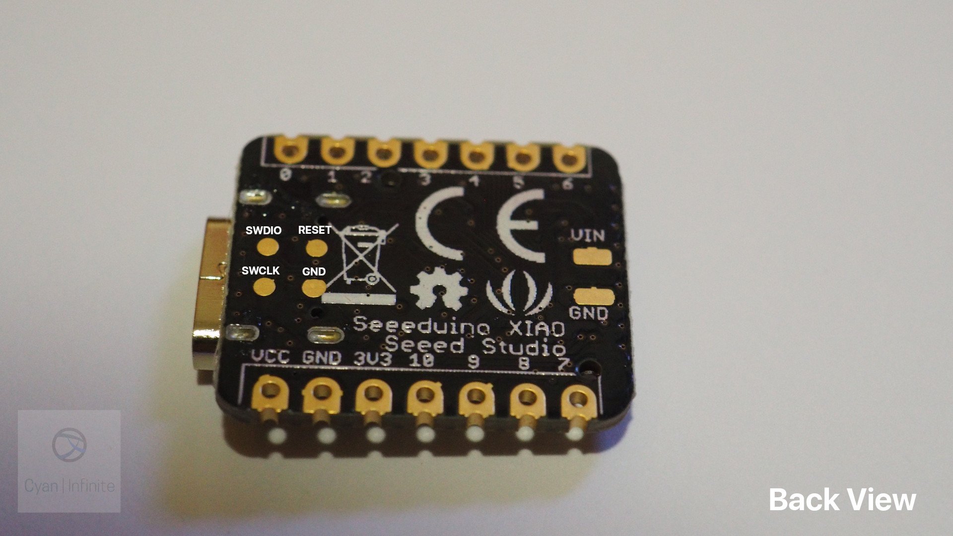
Entering Bootloader
Download the bootloader for the Xiao microcontroller here. After that, connect the Xiao to the computer.
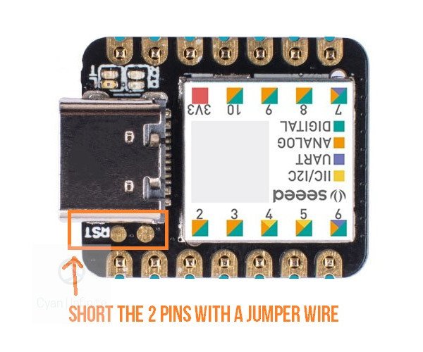
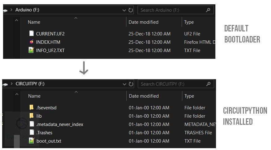
Enter Bootloader mode by shorting the reset pin twice with a jumper wire. A new window Arduino (F:) would appear.
Installation
Drag the Xiao Bootloader uf2 file into the new window. The window would then close and reopen as CIRCUITPY (F:). With that, CircuitPython has successfully being installed!
Mu Editor

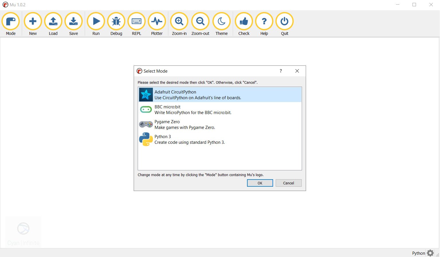
After that, download the Mu editor here, run the setup and launch the application. (If you are using the portable version, extract the zip file and run Launch Mu.bat by double clicking.) Select Adafruit CircuitPython and click OK.
Pulsating World!
We would be downloading a pulsating led example as a Hello, World! example. Copy & paste the following code below into the editor:
import time
import board
from digitalio import DigitalInOut, Direction

led = DigitalInOut(board.D13)       # Initialise Pin 13 as led
led.direction = Direction.OUTPUT    # Set led as output

def setLed(state, delayT):          # Function to set LED state
    led.value = state
    time.sleep(delayT)

def pulsate():                      # Function to pulsate the LED
    setLed(False, 0.3)              # LED on the Xiao is Active Low, turning ON only when 0 is written
    setLed(True,2)

while True:
    pulsate()
After that, save the file as main.py on the Xiao Directory (Most probably in F:\CIRCUITPY). And Viola, the Xiao onboard LED would start pulsating!
More tutorials on CircuitPython could be found here.
Projects
Projects & tutorials related to the Xiao microcontroller would be listed here, stay tune for them here!
Troubleshooting
The Xiao is powered & connected to the PC, but it is not detected by the PC?
Double check the Type C cable, as not all the cable is able to transfer data. Try it with another Type C cable. (Ensure that the driver has been installed beforehand too if it worked previously)
I flashed the CircuitPython Bootloader to code in Python, but I want to return to Arduino. Is it possible?
Yes, it’s quite straightfoward. Just upload the Arduino code as usual, it would overwrite the CircuitPython bootloader. (By selecting the Xiao microcontroller port on the Arduino)
Help, the Arduino port has disappeared while uploading on Arduino!
It may happen when the uploading of the code has been interrupted. You can enter the DF bootloader mode, and the port should reappear again.
References
- https://github.com/Seeed-Studio/ArduinoCore-samd/blob/master/variants/XIAO_m0/variant.cpp
- https://wiki.seeedstudio.com/Seeeduino-XIAO
- https://learn.adafruit.com/welcome-to-circuitpython
I’m trying to use the XIAO to play a WAV file, but I’m having no luck. How do you recommend I proceed?
I tried using the WAV playback code on this page:
https://learn.adafruit.com/circuitpython-essentials/circuitpython-audio-out
Hi Dani,
Can you post the schematics of the circuit?
What is the default output frequency on the analog pins
Hi, the frequency can be found in the PWM Operation section of the specification sheet: https://files.seeedstudio.com/wiki/Seeeduino-XIAO/res/ATSAMD21G18A-MU-Datasheet.pdf
If you want to change the PWM frequency, you may want to refer to this page: https://shawnhymel.com/1710/arduino-zero-samd21-raw-pwm-using-cmsis/
Anyone have any idea what the power draw limitations on the pins? Specially the DAC pin.
Hi, thanks for the guide I found it really helpful in getting started!
One potential issue I have come across is that I do not seem to be able to get PWM output from pin 6 on the xiao. All other pins can produce PWM no worries.
I did a little looking around and I found this issue on the seeduino forum https://forum.seeedstudio.com/t/xiao-pwm-servo-library-problem-report/251866.
In the post the issue is related to the timer handlers and seems to have been resolved for the arduino configuration.
My setup is with circuitpython for the time being, any advice on how to get around this problem?
For reference the error message I receive is : ValueError: All timers for this pin are in use
My suspicion is that the circuitpython pulseio module is at fault – does anyone know how/where I can get the source code?
When I try to control servos with the XIAO via the USB serial (with a power bus feeding the servos enough current), they operate very jerky and delayed. Any ideas to what might be the problem?
Hi Munkpuppy, do you have the schematics of the setup and the code that was used? It is hard to determine the issue without additional information.