Having any trouble figuring out how to interface this particular SPI 0.96″ OLED Display with 6 pins? This tutorial is for you!

Brief Overview
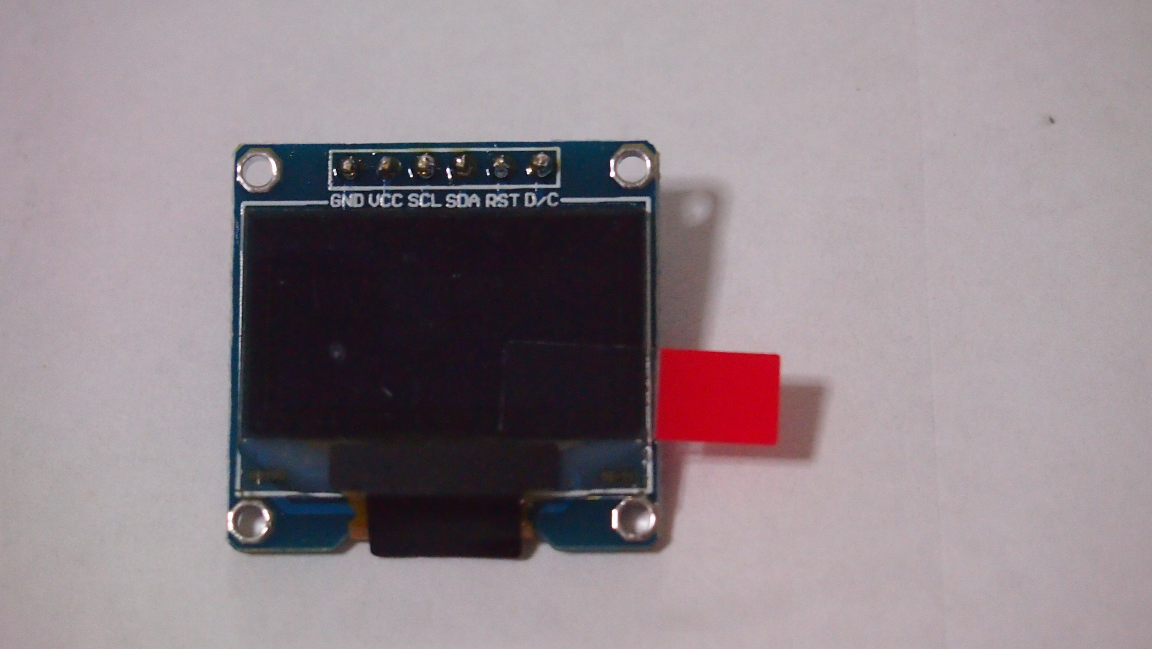
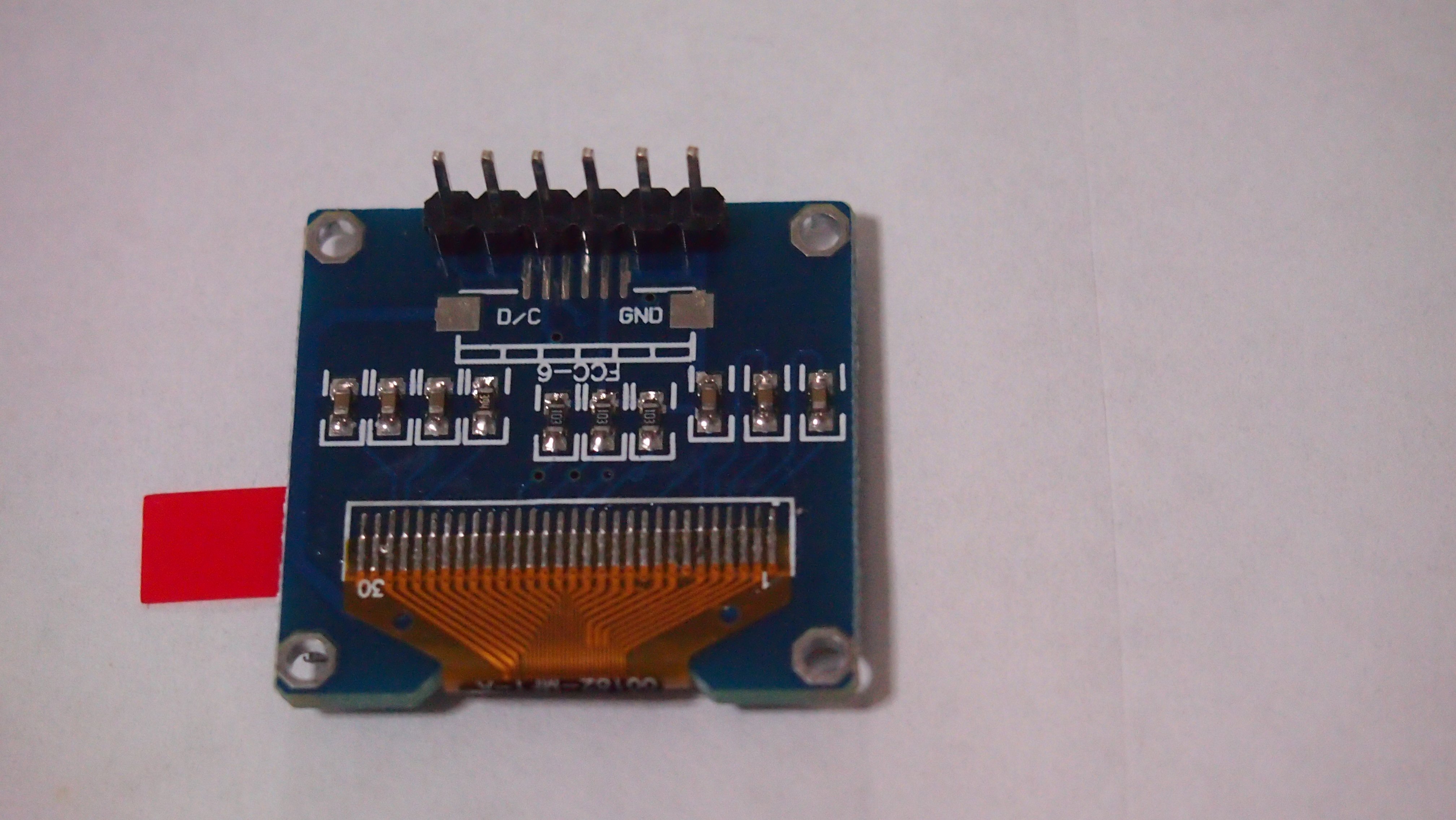
Looking almost identical to the I2C version of the 0.96″ OLED display, this display have 6 pins instead of 4 pins. But what is the key advantage of this SPI 0.96″ OLED Display compared to the I2C one? Speed. Although it have slightly more pins compared to the other one (I2C), SPI is easier to control & is relatively faster in terms of communication.
Interfacing
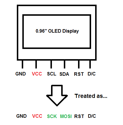
For interfacing the OLED to a microcontroller, the SCL pin is treated as the CLK/SCK pin, the SDA pin as MOSI pin. The Vcc pin can be powered by either 5V or 3.3V, but I prefer powering the display at 3.3V.
Testing
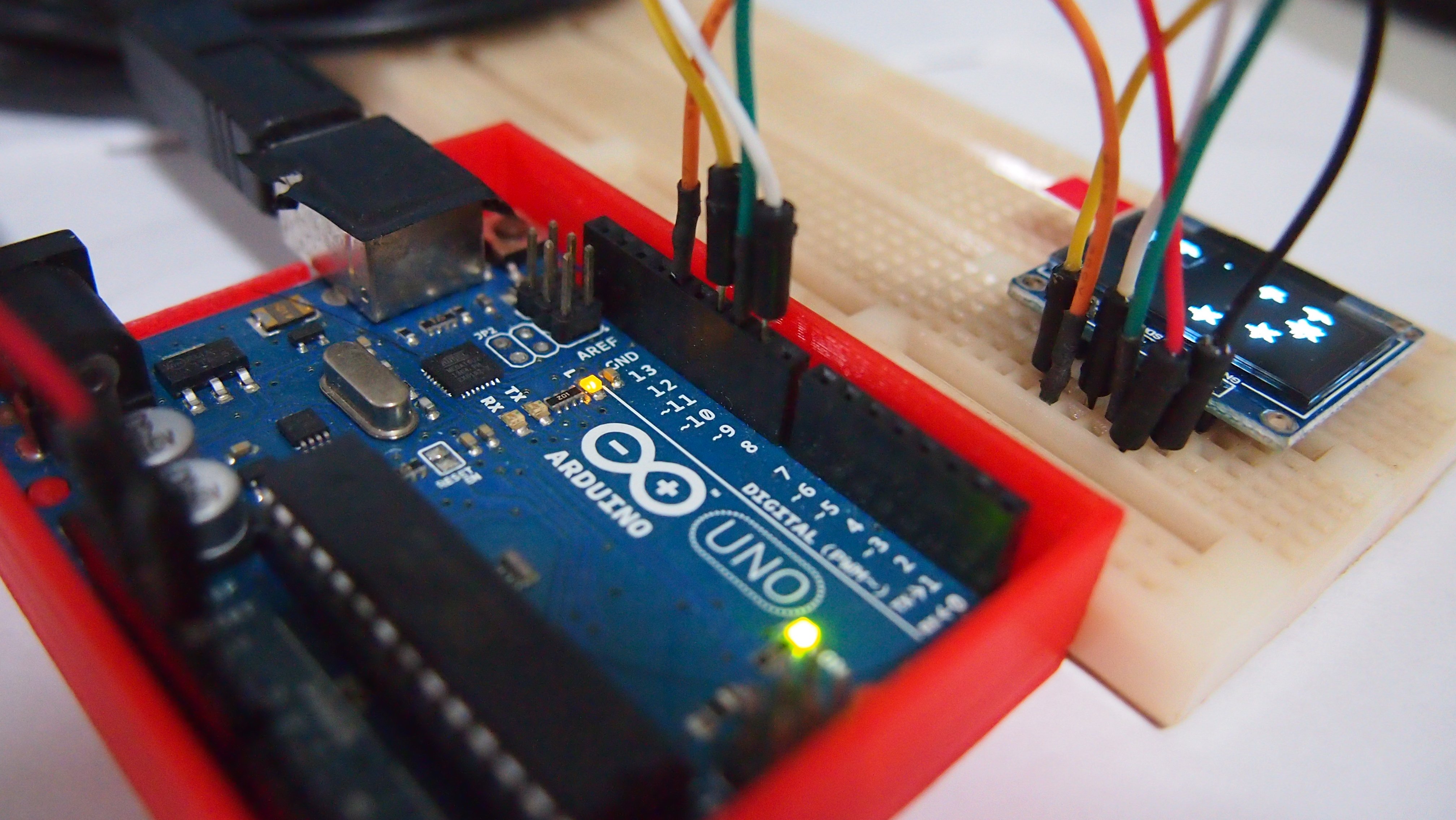
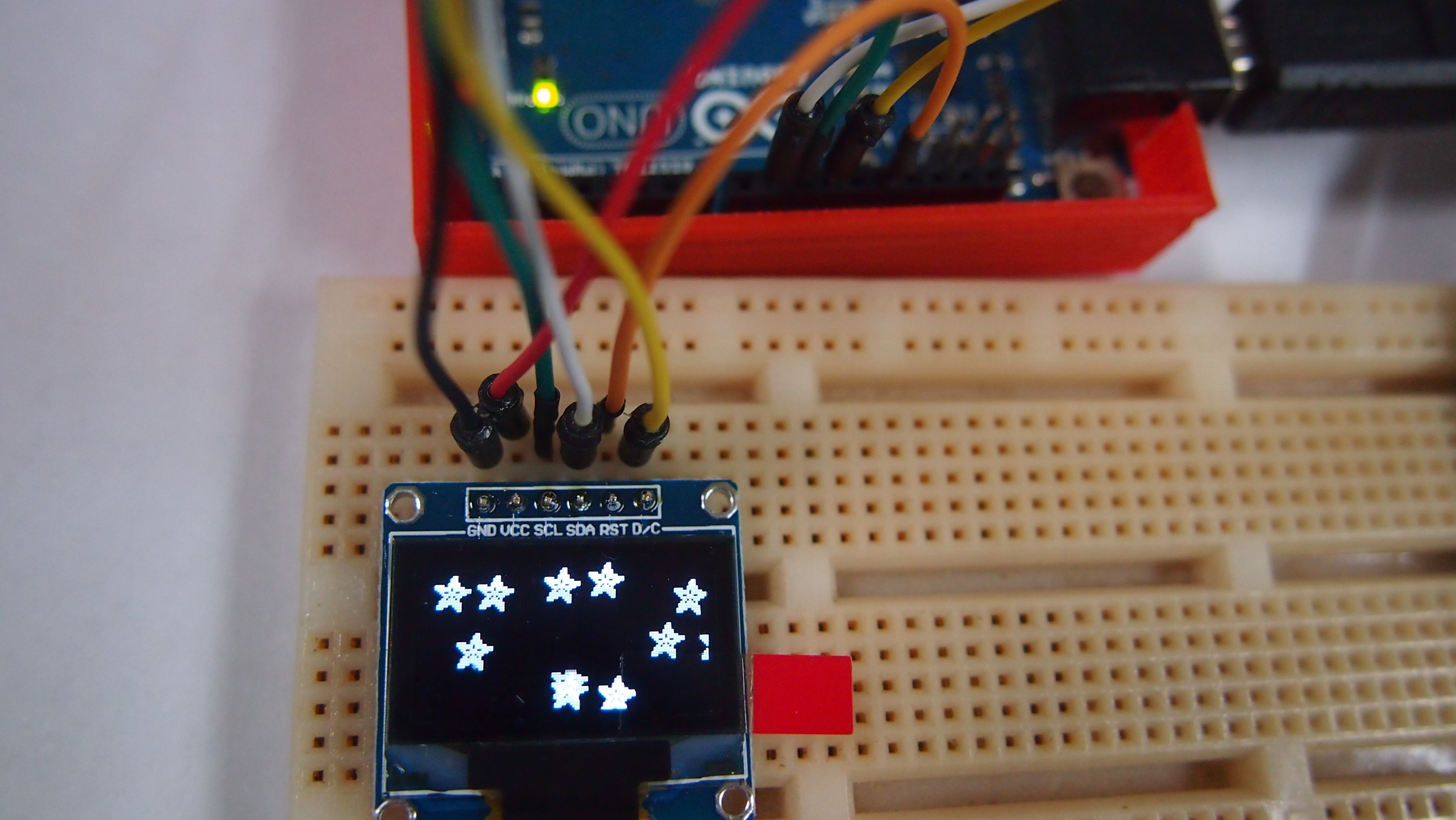
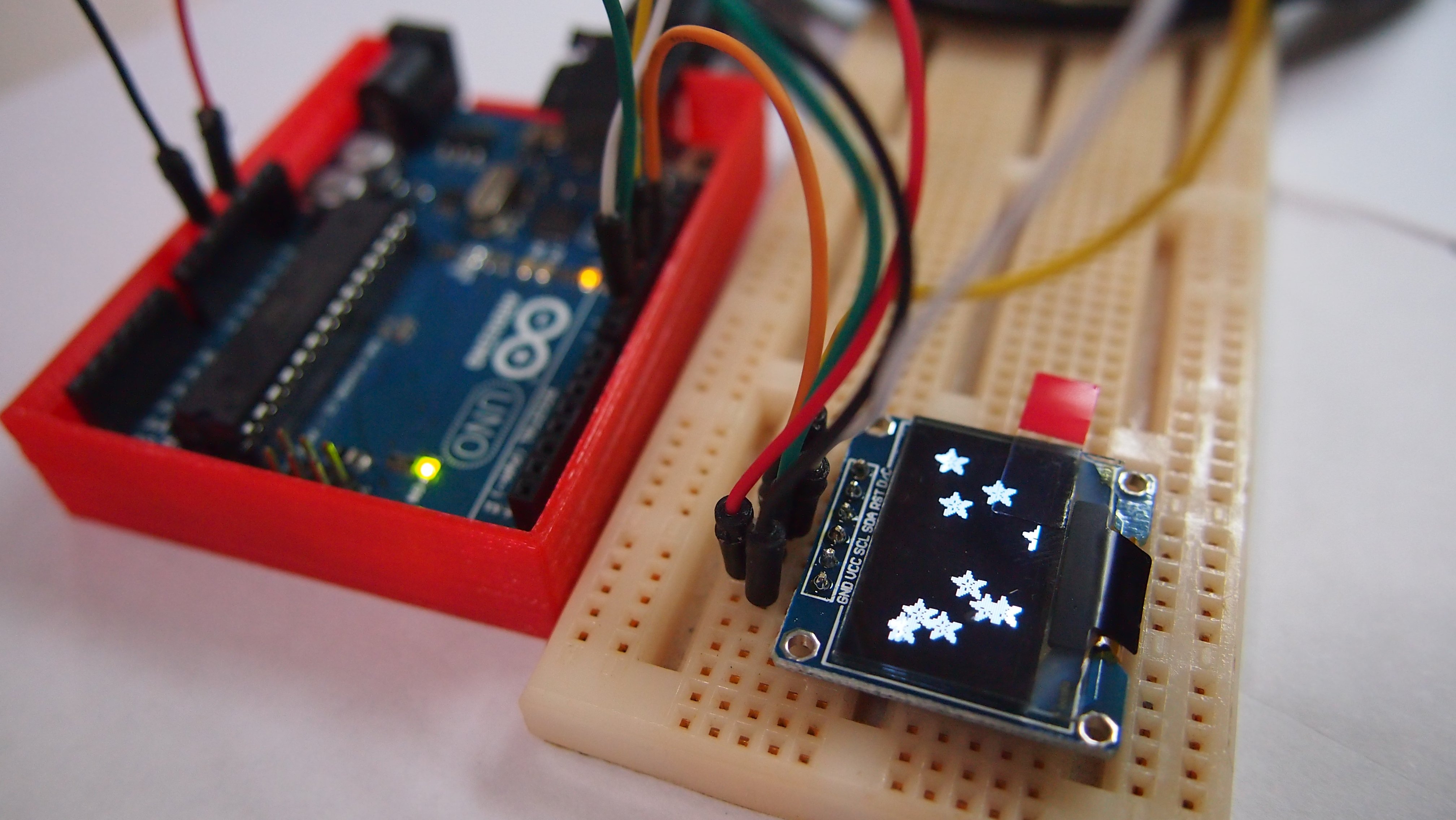
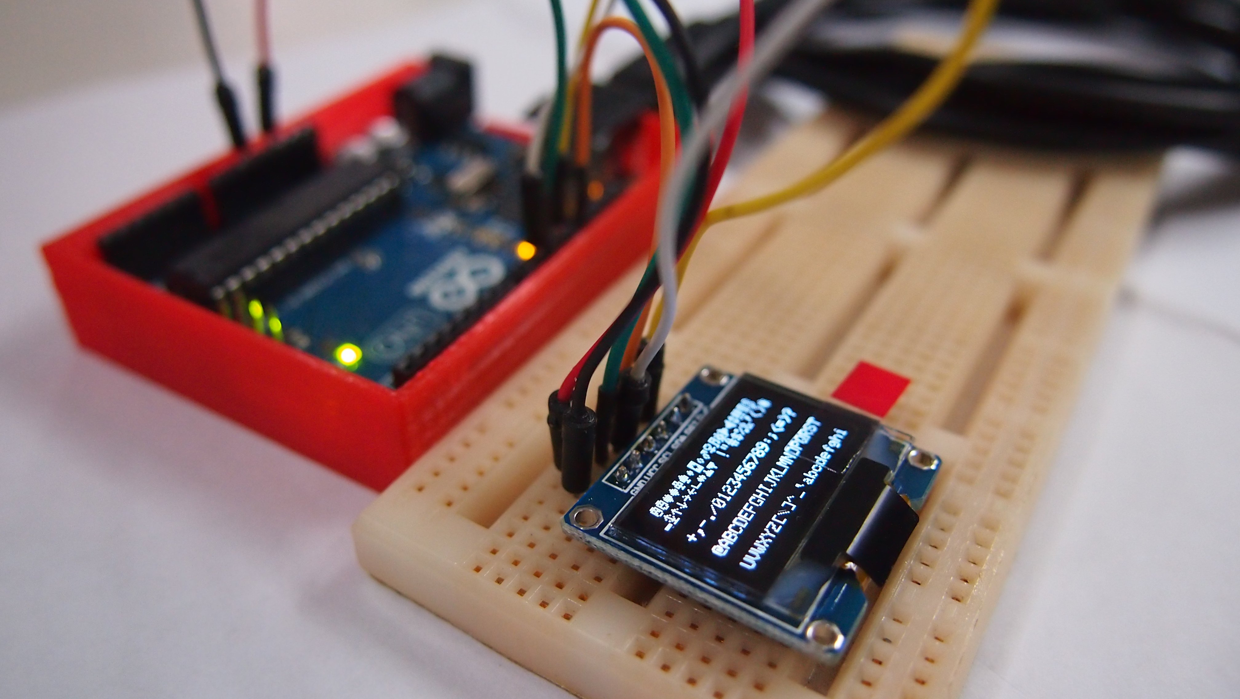
Using Adafruit’s SSD1306 128×64 SPI sample sketch as an example, we would connect the display with the Arduino accordingly:
| Arduino Pins | OLED Display Pins |
|---|---|
| Vcc | Vcc |
| GND | GND |
| D10 | SCL |
| D9 | SDA |
| D13 | RST |
| D11 | D/C |
Download the following libraries & place it in your Arduino Librariy directory:
Adafruit’s GFX library: https://github.com/adafruit/Adafruit-GFX-Library
Adafruit’s SSD1306 library: https://github.com/adafruit/Adafruit_SSD1306
After that, upload the Adafruit’s SSD1306 128×64 SPI sample sketch into your Arduino board & the display should be running!