Contents
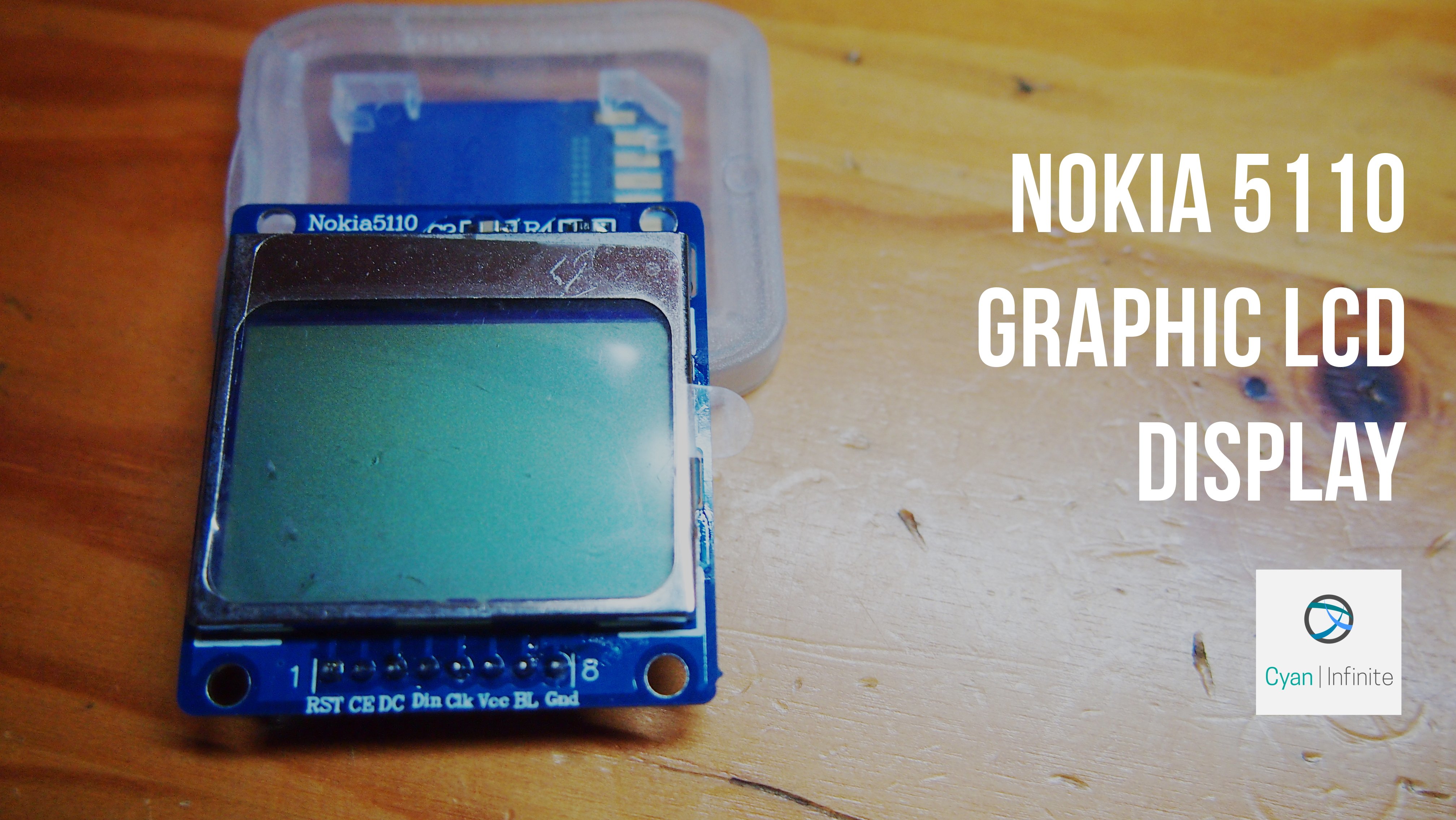
The classical Nokia 5110 graphic display screen has a resolution of 84 x 48 pixels & can be used to display simple graphics & data in various projects. Therefore, in this post, we’ll be exploring how we will interface the Nokia 5110 display with the Arduino, firstly through the hard(ware) way and later, using a library.
Overview
These displays were once used in the Nokia 5110 cellphone (sold during the 90’s) as a display, but now they are more commonly used in projects. Having a back light (actually just LEDs shining at the left & right sides of the display), this monochrome display is powered by a PCD8544 controller/driver & it uses SPI for communications.
Parts Required
For this tutorial, we would be using:
- Arduino Uno x 1
- Jumper wires (A few)
- 10KΩ Resistors x 4
- 1KΩ Resistor x 1
- 330Ω Resistor x 1
- Breadboard x 1
Hooking it up
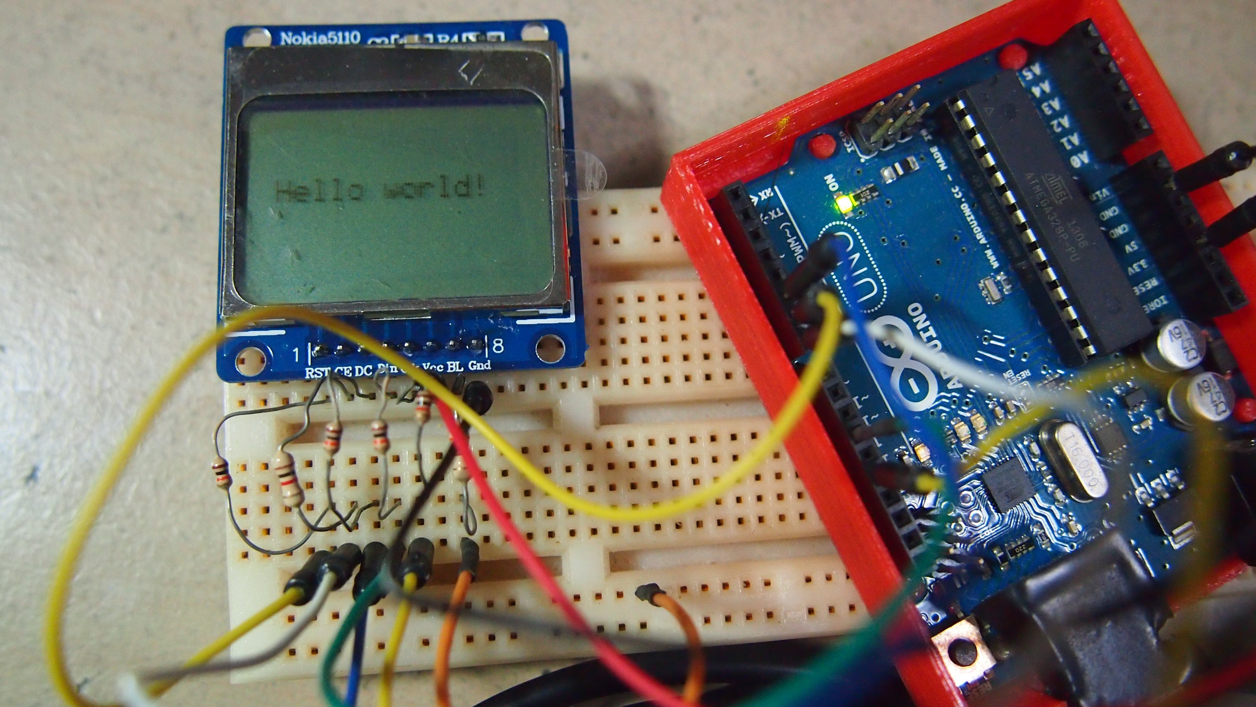
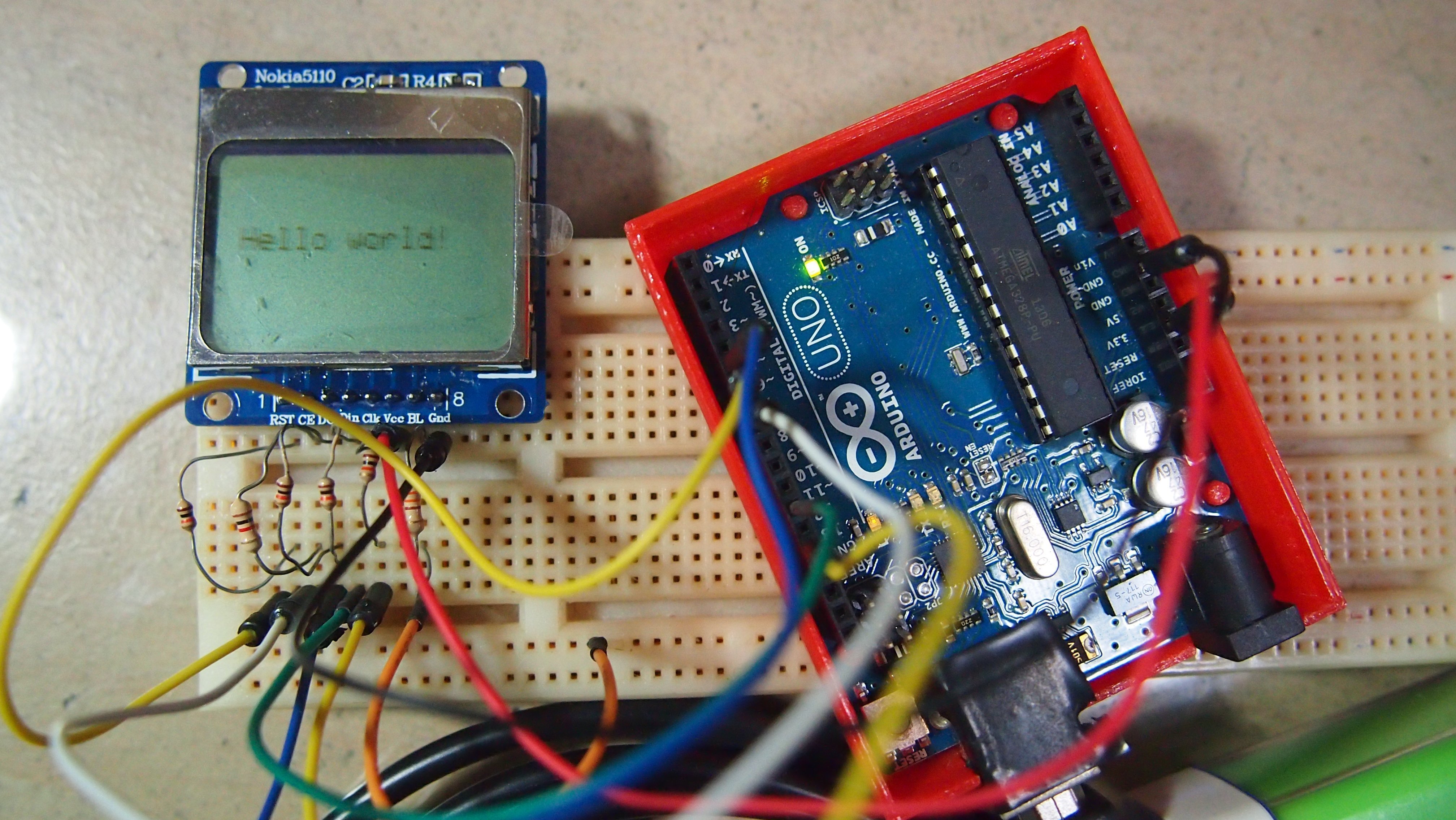
For the data transmission pins, Clk and Din (MOSI), we’ll use the Arduino’s hardware SPI pins, which will help to achieve a faster data transfer. The chip enable/select (CE), reset (RST), and a data/command (DC) pins will be connected to the various digital I/O pin. Lastly, the LED pin should be connected to a PWM-capable Arduino pin, so we can adjust the backlight accordingly, or you can connect it to the 3.3V terminal with a 330Ω Resistor.
However, for this Nokia 5110 LCD display, it has a maximum input voltage of 3.6V, so we can’t hook up a standard 5V Arduino directly. We need to perform level shifting, so we’ll be using limiting resistors to limit the voltage. (Actually a level shifter can be used, but we wouldn’t be using it here today.)
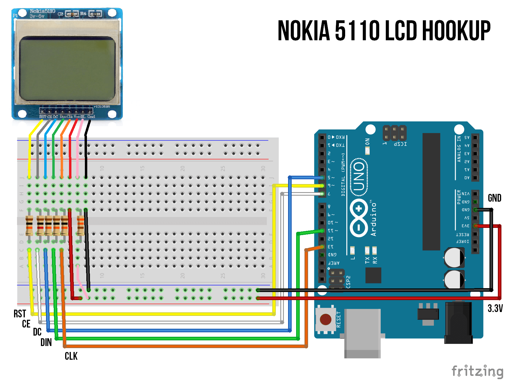
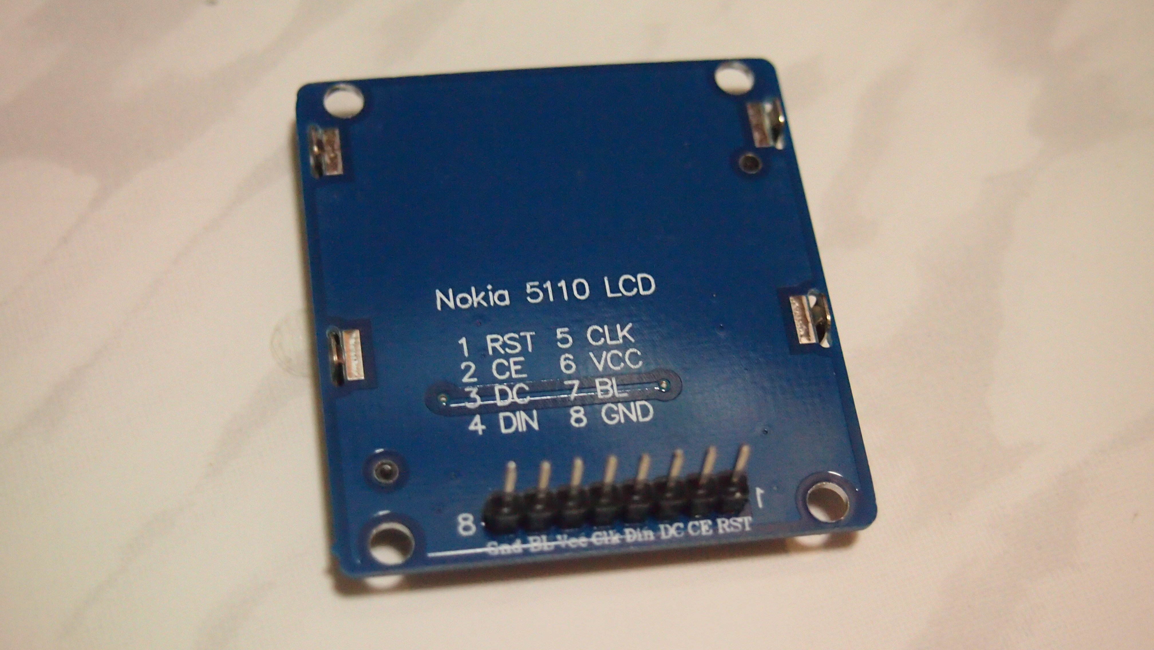
For each signal, there is an inline resistor connected before each pin (other than the Vcc & Gnd pins). Connect a 10kΩ resistors between the RST, DC, Din & Clk pins; a 1kΩ resistor between CE and pin 7. Add a 330Ω resistor between the 3.3V rail and the BL (Backlight) pin. (Optional) Below is the summary of the connections:
LCD Pin |
Arduino Pin |
Limiting Resistor |
|---|---|---|
| RST | 6 | 10kΩ |
| CE (Chip Enable) | 7 | 1kΩ |
| DC (Data/Command) | 5 | 10kΩ |
| Din (MOSI) | 11 | 10kΩ |
| Clk | 13 | 10kΩ |
| Vcc | 3.3V | – |
| BL | 3.3V | 330Ω |
| Gnd | Gnd | – |
Hard(ware) Way

Before we jump in & use a library to control the display, we’ll be using the commands available in the PCD8544 driver to display some simple text. We’ll be modifying the code written by Julian Ilett (Thanks!) and animating the text instead. The codes are as shown below:
//nokia5110disp.ino

#define RST 6
#define CE 7
#define DC 5
#define DIN 11
#define CLK 13

#include "font.h";
void LcdString(char *characters)
{
  while(*characters) LcdWriteCharacter(*characters++);
}

void LcdWriteCharacter(char character)
{
  for(int i=0; i<5; i++) LcdWriteData(ASCII[character - 0x20][i]);
  LcdWriteData(0x00);
}

void LcdWriteData(byte dat)
{
  digitalWrite(DC, HIGH); //DC pin is low for commands
  digitalWrite(CE, LOW);
  shiftOut(DIN, CLK, MSBFIRST, dat); //transmit serial data
  digitalWrite(CE, HIGH);
}

void LcdXY(int x, int y)
{
  LcdWriteCmd(0x80 | x);  // Column.
  LcdWriteCmd(0x40 | y);  // Row.
}

void LcdWriteCmd(byte cmd)
{
  digitalWrite(DC, LOW); //DC pin is low for commands
  digitalWrite(CE, LOW);
  shiftOut(DIN, CLK, MSBFIRST, cmd); //transmit serial data
  digitalWrite(CE, HIGH);
}

void setup()
{
  pinMode(RST, OUTPUT);
  pinMode(CE, OUTPUT);
  pinMode(DC, OUTPUT);
  pinMode(DIN, OUTPUT);
  pinMode(CLK, OUTPUT);
  digitalWrite(RST, LOW);
  digitalWrite(RST, HIGH);

  LcdWriteCmd(0x21);  // LCD extended commands
  LcdWriteCmd(0xB8);  // set LCD Vop (contrast), change the value if it's too light or dark
  LcdWriteCmd(0x04);  // set temp coefficent
  LcdWriteCmd(0x14);  // LCD bias mode 1:40
  LcdWriteCmd(0x20);  // LCD basic commands
  LcdWriteCmd(0x0C);  // LCD normal video

  for(int i=0; i<504; i++) LcdWriteData(0x00); // clear LCD
}

void loop()
{
  for(int j=0;j<14;j++){
     for(int i=0; i<504; i++){ LcdWriteData(0x00); }// clear LCD
  LcdXY(j,2);
  LcdWriteString("Hello world!");

  }
    for(int j=14;j>0;j--){
     for(int i=0; i<504; i++){ LcdWriteData(0x00); }// clear LCD
  LcdXY(j,2);
  LcdWriteString("Hello world!");
  //  LcdWriteString(dtostrf(j,5,1,"string"));

  }
}
//font.h

#include <Arduino.h>

static const byte ASCII[][5] =
{
 {0x00, 0x00, 0x00, 0x00, 0x00} // 20
,{0x00, 0x00, 0x5f, 0x00, 0x00} // 21 !
,{0x00, 0x07, 0x00, 0x07, 0x00} // 22 "
,{0x14, 0x7f, 0x14, 0x7f, 0x14} // 23 #
,{0x24, 0x2a, 0x7f, 0x2a, 0x12} // 24 $
,{0x23, 0x13, 0x08, 0x64, 0x62} // 25 %
,{0x36, 0x49, 0x55, 0x22, 0x50} // 26 &
,{0x00, 0x05, 0x03, 0x00, 0x00} // 27 '
,{0x00, 0x1c, 0x22, 0x41, 0x00} // 28 (
,{0x00, 0x41, 0x22, 0x1c, 0x00} // 29 )
,{0x14, 0x08, 0x3e, 0x08, 0x14} // 2a *
,{0x08, 0x08, 0x3e, 0x08, 0x08} // 2b +
,{0x00, 0x50, 0x30, 0x00, 0x00} // 2c ,
,{0x08, 0x08, 0x08, 0x08, 0x08} // 2d -
,{0x00, 0x60, 0x60, 0x00, 0x00} // 2e .
,{0x20, 0x10, 0x08, 0x04, 0x02} // 2f /
,{0x3e, 0x51, 0x49, 0x45, 0x3e} // 30 0
,{0x00, 0x42, 0x7f, 0x40, 0x00} // 31 1
,{0x42, 0x61, 0x51, 0x49, 0x46} // 32 2
,{0x21, 0x41, 0x45, 0x4b, 0x31} // 33 3
,{0x18, 0x14, 0x12, 0x7f, 0x10} // 34 4
,{0x27, 0x45, 0x45, 0x45, 0x39} // 35 5
,{0x3c, 0x4a, 0x49, 0x49, 0x30} // 36 6
,{0x01, 0x71, 0x09, 0x05, 0x03} // 37 7
,{0x36, 0x49, 0x49, 0x49, 0x36} // 38 8
,{0x06, 0x49, 0x49, 0x29, 0x1e} // 39 9
,{0x00, 0x36, 0x36, 0x00, 0x00} // 3a :
,{0x00, 0x56, 0x36, 0x00, 0x00} // 3b ;
,{0x08, 0x14, 0x22, 0x41, 0x00} // 3c <
,{0x14, 0x14, 0x14, 0x14, 0x14} // 3d =
,{0x00, 0x41, 0x22, 0x14, 0x08} // 3e >
,{0x02, 0x01, 0x51, 0x09, 0x06} // 3f ?
,{0x32, 0x49, 0x79, 0x41, 0x3e} // 40 @
,{0x7e, 0x11, 0x11, 0x11, 0x7e} // 41 A
,{0x7f, 0x49, 0x49, 0x49, 0x36} // 42 B
,{0x3e, 0x41, 0x41, 0x41, 0x22} // 43 C
,{0x7f, 0x41, 0x41, 0x22, 0x1c} // 44 D
,{0x7f, 0x49, 0x49, 0x49, 0x41} // 45 E
,{0x7f, 0x09, 0x09, 0x09, 0x01} // 46 F
,{0x3e, 0x41, 0x49, 0x49, 0x7a} // 47 G
,{0x7f, 0x08, 0x08, 0x08, 0x7f} // 48 H
,{0x00, 0x41, 0x7f, 0x41, 0x00} // 49 I
,{0x20, 0x40, 0x41, 0x3f, 0x01} // 4a J
,{0x7f, 0x08, 0x14, 0x22, 0x41} // 4b K
,{0x7f, 0x40, 0x40, 0x40, 0x40} // 4c L
,{0x7f, 0x02, 0x0c, 0x02, 0x7f} // 4d M
,{0x7f, 0x04, 0x08, 0x10, 0x7f} // 4e N
,{0x3e, 0x41, 0x41, 0x41, 0x3e} // 4f O
,{0x7f, 0x09, 0x09, 0x09, 0x06} // 50 P
,{0x3e, 0x41, 0x51, 0x21, 0x5e} // 51 Q
,{0x7f, 0x09, 0x19, 0x29, 0x46} // 52 R
,{0x46, 0x49, 0x49, 0x49, 0x31} // 53 S
,{0x01, 0x01, 0x7f, 0x01, 0x01} // 54 T
,{0x3f, 0x40, 0x40, 0x40, 0x3f} // 55 U
,{0x1f, 0x20, 0x40, 0x20, 0x1f} // 56 V
,{0x3f, 0x40, 0x38, 0x40, 0x3f} // 57 W
,{0x63, 0x14, 0x08, 0x14, 0x63} // 58 X
,{0x07, 0x08, 0x70, 0x08, 0x07} // 59 Y
,{0x61, 0x51, 0x49, 0x45, 0x43} // 5a Z
,{0x00, 0x7f, 0x41, 0x41, 0x00} // 5b [
,{0x02, 0x04, 0x08, 0x10, 0x20} // 5c ¥
,{0x00, 0x41, 0x41, 0x7f, 0x00} // 5d ]
,{0x04, 0x02, 0x01, 0x02, 0x04} // 5e ^
,{0x40, 0x40, 0x40, 0x40, 0x40} // 5f _
,{0x00, 0x01, 0x02, 0x04, 0x00} // 60 `
,{0x20, 0x54, 0x54, 0x54, 0x78} // 61 a
,{0x7f, 0x48, 0x44, 0x44, 0x38} // 62 b
,{0x38, 0x44, 0x44, 0x44, 0x20} // 63 c
,{0x38, 0x44, 0x44, 0x48, 0x7f} // 64 d
,{0x38, 0x54, 0x54, 0x54, 0x18} // 65 e
,{0x08, 0x7e, 0x09, 0x01, 0x02} // 66 f
,{0x0c, 0x52, 0x52, 0x52, 0x3e} // 67 g
,{0x7f, 0x08, 0x04, 0x04, 0x78} // 68 h
,{0x00, 0x44, 0x7d, 0x40, 0x00} // 69 i
,{0x20, 0x40, 0x44, 0x3d, 0x00} // 6a j
,{0x7f, 0x10, 0x28, 0x44, 0x00} // 6b k
,{0x00, 0x41, 0x7f, 0x40, 0x00} // 6c l
,{0x7c, 0x04, 0x18, 0x04, 0x78} // 6d m
,{0x7c, 0x08, 0x04, 0x04, 0x78} // 6e n
,{0x38, 0x44, 0x44, 0x44, 0x38} // 6f o
,{0x7c, 0x14, 0x14, 0x14, 0x08} // 70 p
,{0x08, 0x14, 0x14, 0x18, 0x7c} // 71 q
,{0x7c, 0x08, 0x04, 0x04, 0x08} // 72 r
,{0x48, 0x54, 0x54, 0x54, 0x20} // 73 s
,{0x04, 0x3f, 0x44, 0x40, 0x20} // 74 t
,{0x3c, 0x40, 0x40, 0x20, 0x7c} // 75 u
,{0x1c, 0x20, 0x40, 0x20, 0x1c} // 76 v
,{0x3c, 0x40, 0x30, 0x40, 0x3c} // 77 w
,{0x44, 0x28, 0x10, 0x28, 0x44} // 78 x
,{0x0c, 0x50, 0x50, 0x50, 0x3c} // 79 y
,{0x44, 0x64, 0x54, 0x4c, 0x44} // 7a z
,{0x00, 0x08, 0x36, 0x41, 0x00} // 7b {
,{0x00, 0x00, 0x7f, 0x00, 0x00} // 7c |
,{0x00, 0x41, 0x36, 0x08, 0x00} // 7d }
,{0x10, 0x08, 0x08, 0x10, 0x08} // 7e ←
,{0x78, 0x46, 0x41, 0x46, 0x78} // 7f →
};
For more information & examples, you can visit the following:
- Arduino Website: http://playground.arduino.cc/Code/PCD8544
Library
![]()
Now, we’ll be using Adafruit’s PCD8544 Nokia 5110 LCD library to control the library. The library can be downloaded here: https://github.com/adafruit/Adafruit-PCD8544-Nokia-5110-LCD-library. Download & install the library. (Make sure you have the Adafruit GFX library downloaded & installed too as this library will provide the graphics functionality of the Nokia 5110 display.) After that, copy the code below. The code below is actually the example sketch of the PCD8544 library, but I modified the code a little. (Like changing pin numbers, modifying comments, etc.)
/*********************************************************************
This is an example sketch for our Monochrome Nokia 5110 LCD Displays

  Pick one up today in the adafruit shop!
  ------> http://www.adafruit.com/products/338

These displays use SPI to communicate, 4 or 5 pins are required to
interface

Adafruit invests time and resources providing this open source code,
please support Adafruit and open-source hardware by purchasing
products from Adafruit!

Written by Limor Fried/Ladyada  for Adafruit Industries.
BSD license, check license.txt for more information
All text above, and the splash screen must be included in any redistribution
*********************************************************************/

#include <SPI.h>
#include <Adafruit_GFX.h>
#include <Adafruit_PCD8544.h>

// Software SPI (slower updates, more flexible pin options):
// pin 13 - Serial clock out (CLK/SCLK)
// pin 11 - Serial data out (DIN)
// pin 5 - Data/Command select (D/C)
// pin 7 - LCD chip select (CS) [Same as Chip Enable(CE)]
// pin 6 - LCD reset (RST)
// BL - Backlight: Connect a 330ohm resistor before connecting to 3.3V pin [Optional]
Adafruit_PCD8544 display = Adafruit_PCD8544(13, 11, 5, 7, 6);

// Hardware SPI (faster, but must use certain hardware pins):
// SCK is LCD serial clock (SCLK) - this is pin 13 on Arduino Uno
// MOSI is LCD DIN - this is pin 11 on an Arduino Uno
// pin 5 - Data/Command select (D/C)
// pin 7 - LCD chip select (CS)
// pin 6 - LCD reset (RST)
// Adafruit_PCD8544 display = Adafruit_PCD8544(5, 4, 3);
// Note with hardware SPI MISO and SS pins aren't used but will still be read
// and written to during SPI transfer.  Be careful sharing these pins!

#define NUMFLAKES 10
#define XPOS 0
#define YPOS 1
#define DELTAY 2


#define LOGO16_GLCD_HEIGHT 16
#define LOGO16_GLCD_WIDTH  16

static const unsigned char PROGMEM logo16_glcd_bmp[] =
{ B00000000, B11000000,
  B00000001, B11000000,
  B00000001, B11000000,
  B00000011, B11100000,
  B11110011, B11100000,
  B11111110, B11111000,
  B01111110, B11111111,
  B00110011, B10011111,
  B00011111, B11111100,
  B00001101, B01110000,
  B00011011, B10100000,
  B00111111, B11100000,
  B00111111, B11110000,
  B01111100, B11110000,
  B01110000, B01110000,
  B00000000, B00110000 };

void setup()   {
  Serial.begin(9600);

  display.begin();
  // init done

  // you can change the contrast around to adapt the display
  // for the best viewing!
  display.setContrast(50);

  display.display(); // show splashscreen
  delay(2000);
  display.clearDisplay();   // clears the screen and buffer

  // draw a single pixel
  display.drawPixel(10, 10, BLACK);
  display.display();
  delay(2000);
  display.clearDisplay();

  // draw many lines
  testdrawline();
  display.display();
  delay(2000);
  display.clearDisplay();

  // draw rectangles
  testdrawrect();
  display.display();
  delay(2000);
  display.clearDisplay();

  // draw multiple rectangles
  testfillrect();
  display.display();
  delay(2000);
  display.clearDisplay();

  // draw mulitple circles
  testdrawcircle();
  display.display();
  delay(2000);
  display.clearDisplay();

  // draw a circle, 10 pixel radius
  display.fillCircle(display.width()/2, display.height()/2, 10, BLACK);
  display.display();
  delay(2000);
  display.clearDisplay();

  testdrawroundrect();
  delay(2000);
  display.clearDisplay();

  testfillroundrect();
  delay(2000);
  display.clearDisplay();

  testdrawtriangle();
  delay(2000);
  display.clearDisplay();

  testfilltriangle();
  delay(2000);
  display.clearDisplay();

  // draw the first ~12 characters in the font
  testdrawchar();
  display.display();
  delay(2000);
  display.clearDisplay();

  // text display tests
  display.setTextSize(1);
  display.setTextColor(BLACK);
  display.setCursor(0,0);
  display.println("Hello, world!");
  display.setTextColor(WHITE, BLACK); // 'inverted' text
  display.println(3.141592);
  display.setTextSize(2);
  display.setTextColor(BLACK);
  display.print("0x"); display.println(0xDEADBEEF, HEX);
  display.display();
  delay(2000);

  // rotation example
  display.clearDisplay();
  display.setRotation(1);  // rotate 90 degrees counter clockwise, can also use values of 2 and 3 to go further.
  display.setTextSize(1);
  display.setTextColor(BLACK);
  display.setCursor(0,0);
  display.println("Rotation");
  display.setTextSize(2);
  display.println("Example!");
  display.display();
  delay(2000);

  // revert back to no rotation
  display.setRotation(0);

  // miniature bitmap display
  display.clearDisplay();
  display.drawBitmap(30, 16,  logo16_glcd_bmp, 16, 16, 1);
  display.display();

  // invert the display
  display.invertDisplay(true);
  delay(1000);
  display.invertDisplay(false);
  delay(1000);

  // draw a bitmap icon and 'animate' movement
  testdrawbitmap(logo16_glcd_bmp, LOGO16_GLCD_WIDTH, LOGO16_GLCD_HEIGHT);
}


void loop() {

}


void testdrawbitmap(const uint8_t *bitmap, uint8_t w, uint8_t h) {
  uint8_t icons[NUMFLAKES][3];
  randomSeed(666);     // whatever seed

  // initialize
  for (uint8_t f=0; f< NUMFLAKES; f++) {
    icons[f][XPOS] = random(display.width());
    icons[f][YPOS] = 0;
    icons[f][DELTAY] = random(5) + 1;

    Serial.print("x: ");
    Serial.print(icons[f][XPOS], DEC);
    Serial.print(" y: ");
    Serial.print(icons[f][YPOS], DEC);
    Serial.print(" dy: ");
    Serial.println(icons[f][DELTAY], DEC);
  }

  while (1) {
    // draw each icon
    for (uint8_t f=0; f< NUMFLAKES; f++) {
      display.drawBitmap(icons[f][XPOS], icons[f][YPOS], logo16_glcd_bmp, w, h, BLACK);
    }
    display.display();
    delay(200);

    // then erase it + move it
    for (uint8_t f=0; f< NUMFLAKES; f++) {
      display.drawBitmap(icons[f][XPOS], icons[f][YPOS],  logo16_glcd_bmp, w, h, WHITE);
      // move it
      icons[f][YPOS] += icons[f][DELTAY];
      // if its gone, reinit
      if (icons[f][YPOS] > display.height()) {
	icons[f][XPOS] = random(display.width());
	icons[f][YPOS] = 0;
	icons[f][DELTAY] = random(5) + 1;
      }
    }
   }
}


void testdrawchar(void) {
  display.setTextSize(1);
  display.setTextColor(BLACK);
  display.setCursor(0,0);

  for (uint8_t i=0; i < 168; i++) {
    if (i == 'n') continue;
    display.write(i);
    //if ((i > 0) && (i % 14 == 0))
      //display.println();
  }
  display.display();
}

void testdrawcircle(void) {
  for (int16_t i=0; i<display.height(); i+=2) {
    display.drawCircle(display.width()/2, display.height()/2, i, BLACK);
    display.display();
  }
}

void testfillrect(void) {
  uint8_t color = 1;
  for (int16_t i=0; i<display.height()/2; i+=3) {
    // alternate colors
    display.fillRect(i, i, display.width()-i*2, display.height()-i*2, color%2);
    display.display();
    color++;
  }
}

void testdrawtriangle(void) {
  for (int16_t i=0; i<min(display.width(),display.height())/2; i+=5) {
    display.drawTriangle(display.width()/2, display.height()/2-i,
                     display.width()/2-i, display.height()/2+i,
                     display.width()/2+i, display.height()/2+i, BLACK);
    display.display();
  }
}

void testfilltriangle(void) {
  uint8_t color = BLACK;
  for (int16_t i=min(display.width(),display.height())/2; i>0; i-=5) {
    display.fillTriangle(display.width()/2, display.height()/2-i,
                     display.width()/2-i, display.height()/2+i,
                     display.width()/2+i, display.height()/2+i, color);
    if (color == WHITE) color = BLACK;
    else color = WHITE;
    display.display();
  }
}

void testdrawroundrect(void) {
  for (int16_t i=0; i<display.height()/2-2; i+=2) {
    display.drawRoundRect(i, i, display.width()-2*i, display.height()-2*i, display.height()/4, BLACK);
    display.display();
  }
}

void testfillroundrect(void) {
  uint8_t color = BLACK;
  for (int16_t i=0; i<display.height()/2-2; i+=2) {
    display.fillRoundRect(i, i, display.width()-2*i, display.height()-2*i, display.height()/4, color);
    if (color == WHITE) color = BLACK;
    else color = WHITE;
    display.display();
  }
}

void testdrawrect(void) {
  for (int16_t i=0; i<display.height()/2; i+=2) {
    display.drawRect(i, i, display.width()-2*i, display.height()-2*i, BLACK);
    display.display();
  }
}

void testdrawline() {
  for (int16_t i=0; i<display.width(); i+=4) {
    display.drawLine(0, 0, i, display.height()-1, BLACK);
    display.display();
  }
  for (int16_t i=0; i<display.height(); i+=4) {
    display.drawLine(0, 0, display.width()-1, i, BLACK);
    display.display();
  }
  delay(250);

  display.clearDisplay();
  for (int16_t i=0; i<display.width(); i+=4) {
    display.drawLine(0, display.height()-1, i, 0, BLACK);
    display.display();
  }
  for (int8_t i=display.height()-1; i>=0; i-=4) {
    display.drawLine(0, display.height()-1, display.width()-1, i, BLACK);
    display.display();
  }
  delay(250);

  display.clearDisplay();
  for (int16_t i=display.width()-1; i>=0; i-=4) {
    display.drawLine(display.width()-1, display.height()-1, i, 0, BLACK);
    display.display();
  }
  for (int16_t i=display.height()-1; i>=0; i-=4) {
    display.drawLine(display.width()-1, display.height()-1, 0, i, BLACK);
    display.display();
  }
  delay(250);

  display.clearDisplay();
  for (int16_t i=0; i<display.height(); i+=4) {
    display.drawLine(display.width()-1, 0, 0, i, BLACK);
    display.display();
  }
  for (int16_t i=0; i<display.width(); i+=4) {
    display.drawLine(display.width()-1, 0, i, display.height()-1, BLACK);
    display.display();
  }
  delay(250);
}
Upload the code, and the display should be running the demo!