Contents
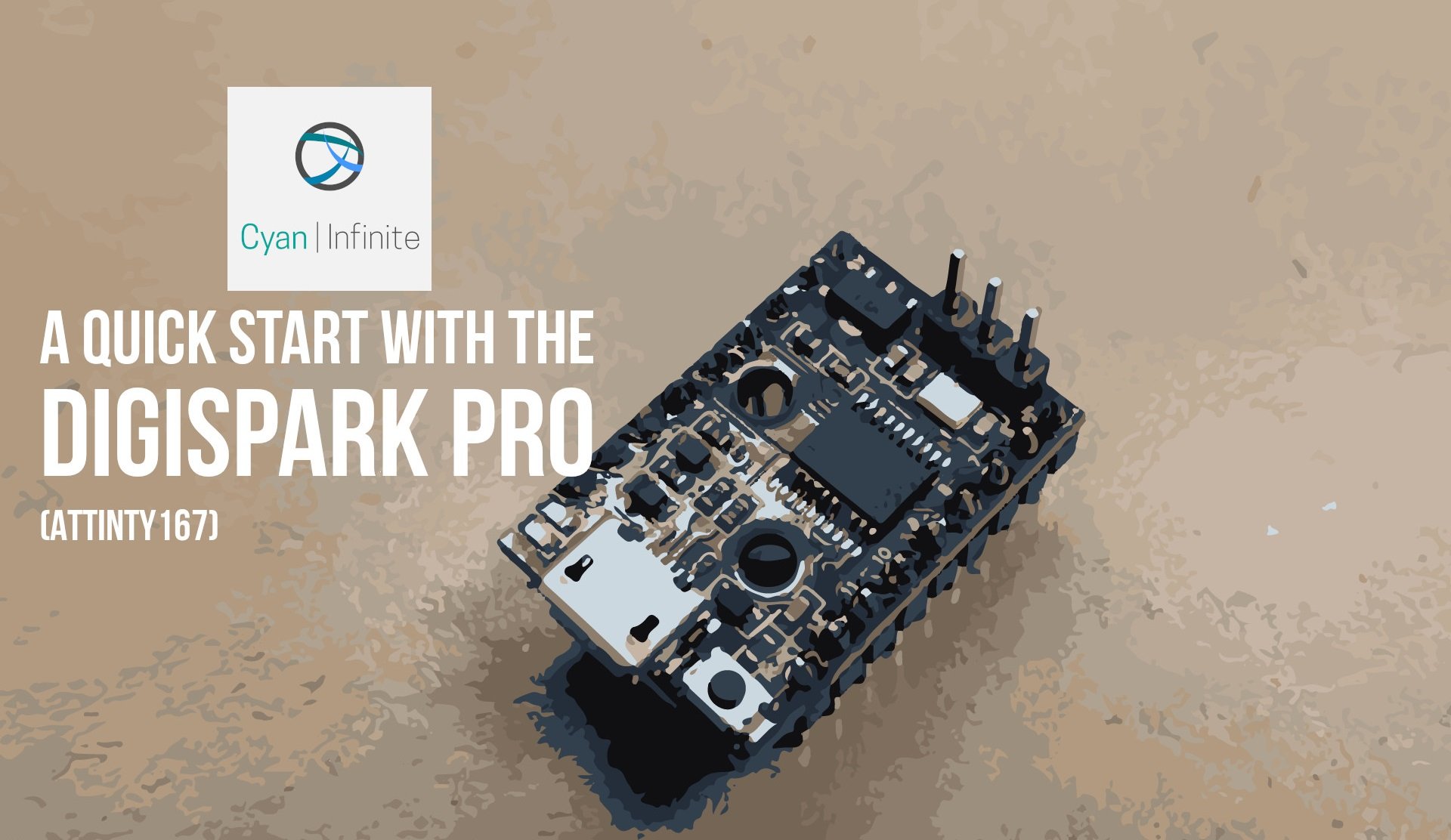
The Digispark Pro (or the ATTiny167 Pro), is another smaller size form microcontroler that one could consider using in their projects that does not require much computational power or GPIO pins, similar to the ATTiny85. In this tutorial, we would be looking at the specifications of the board and the pre-requistes required to get the board running. With that, let’s get started!
Overview
The ATTiny167 Pro is a small form factor microcontroller which utilises the ATTiny167 IC as the main controller running at 16MHz. (Which is faster than the ATtiny85, which runs at 8MHz) It also consists of 13 GPIO pins, with 6 PWM pins, 1 SPI port and 1 I2C port, and the GPIO output is at 5V. This form factor is ideal for projects which are small or does not require too many GPIO pins.
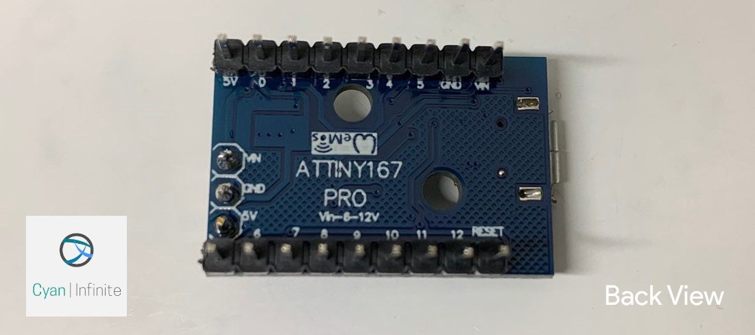
Note: This Digispark Pro used in this tutorial may not be from DigiStump, but the configuration is the same as the cad files are open source.
Specifications
Here are some specifications of the Digispark Pro.
- Dimensions: 26.7mm x 18.3mm x 4mm
- Frequency: 16MHz
- Flash: 14.50KB
- RAM: 512B
- GPIO (output) Max Current: 20 mA
- I2C Pins
- SDA: Pin 0
- SCL: Pin 2
- VIN: 7-12V
- 5V pin Input range: 4.5-5.5v (3v+ may work)
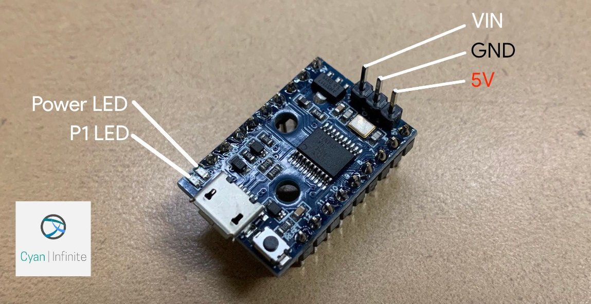
Note: The LED is on Pin 1
Another thing to take note is that the Digispark Pro does not have a hardware serial to USB converter or a hardware serial port, so an external hardware is needed.
Pinouts
The pinout of the board is as follows:
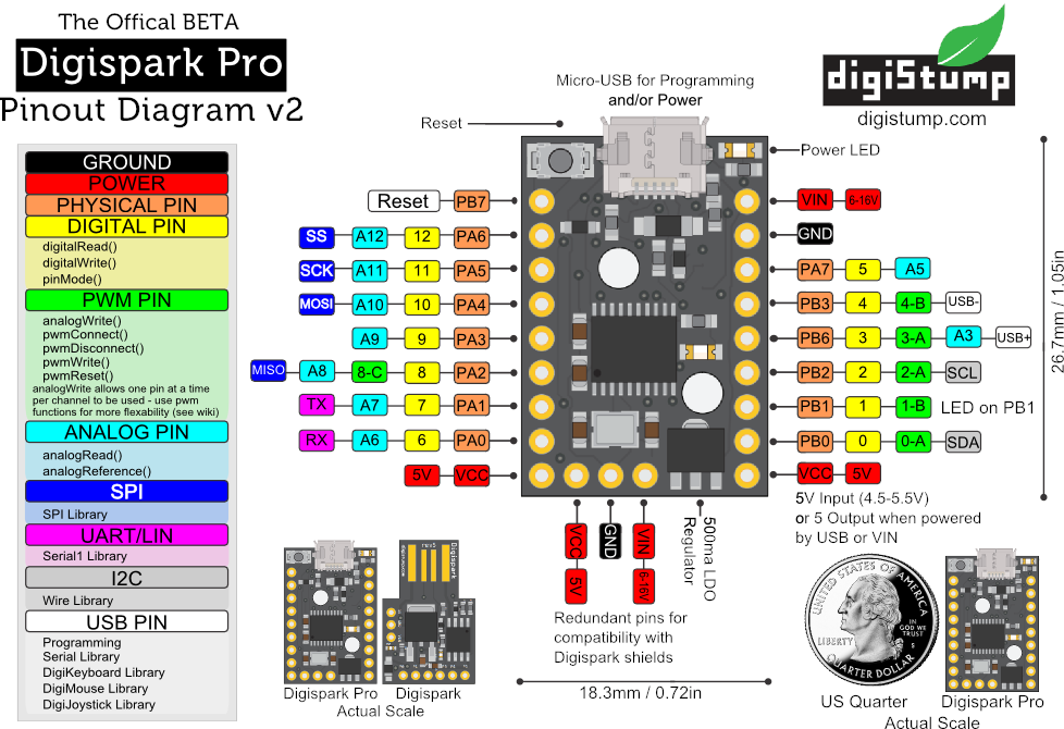
The schematics of it could be found here.
Drivers Installation
Unlike other Arduino, the Digispark Pro may not be recognised when it is first plugged into your computer, which would show up as an unrecognised device (in the device manager) and would not be detected by the Arduino IDE. This could be resolved by installing the relevant drivers required for this microcontroller, which could be found here: https://github.com/digistump/DigistumpArduino/releases/
(If the link above does not work, try this alternate link.)
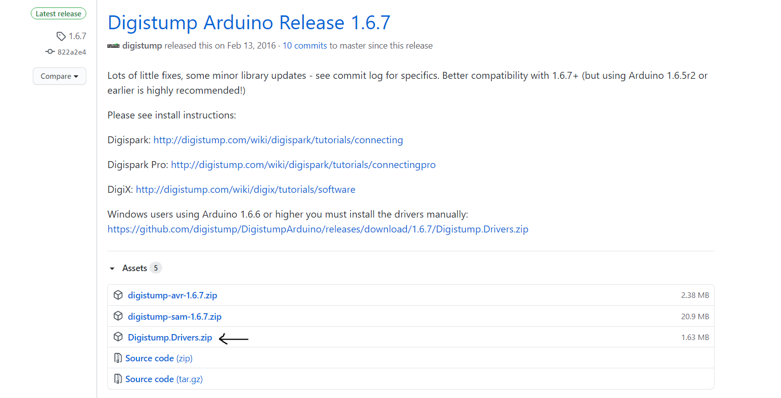
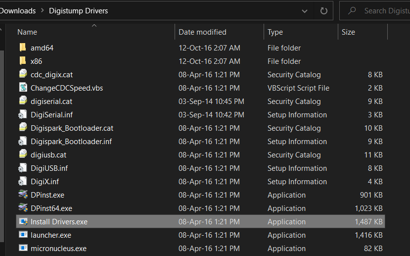
Download the “Digistump.Drivers.zip”, unzip the contents and run “Install Drivers.exe” to begin the driver installation. (If this does not work, try “DPinst64.exe” or “DPinst.exe”.)
The latest version since the time of writing is 1.6.7.
Arduino IDE – Boards Manager
After the drivers for the Digispark Pro has been installed, we would proceed on to setup the board in the Arduino IDE. Open up the preferences menu of Arduino, and append the following to the Additional Boards Manager URL (by clicking on the button beside the textbox):
http://digistump.com/package_digistump_index.json
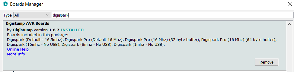
After that, click OK and the URL should be added. Next, goto Board > Board Manager and search for digispark, and install the one by Digistump.
Hello World
The code could be loaded under File > Example > Basic > Blink, the only difference is that we would change the BUILTIN_LED to 1 instead, which is the pin that is connected to the Digispark Pro onboard. Before uploading, ensure that the correct board is selected: select Digispark ( Default – 16.5mhz ) and upload the code to the board.
Note: You do not need to connect the Digispark Pro to the computer when uploading the code, the status terminal at the bottom of the IDE would let you know when to connect the Digispark Pro.
Alternatively, if the board is already connected beforehand, you can just press the reset button onboard when it prompts you to connect the board.
And Viola! The board should be blinking every 1s!
References
- http://digistump.com/wiki/digispark
- https://docs.platformio.org/en/v5.1.1/boards/atmelavr/digispark-pro.html
- http://digistump.com/wiki/digispark/tutorials/connectingpro
- https://github.com/digistump/DigistumpArduino
- https://wiki.liutyi.info/display/ARDUINO/Digispark+Pro