Contents
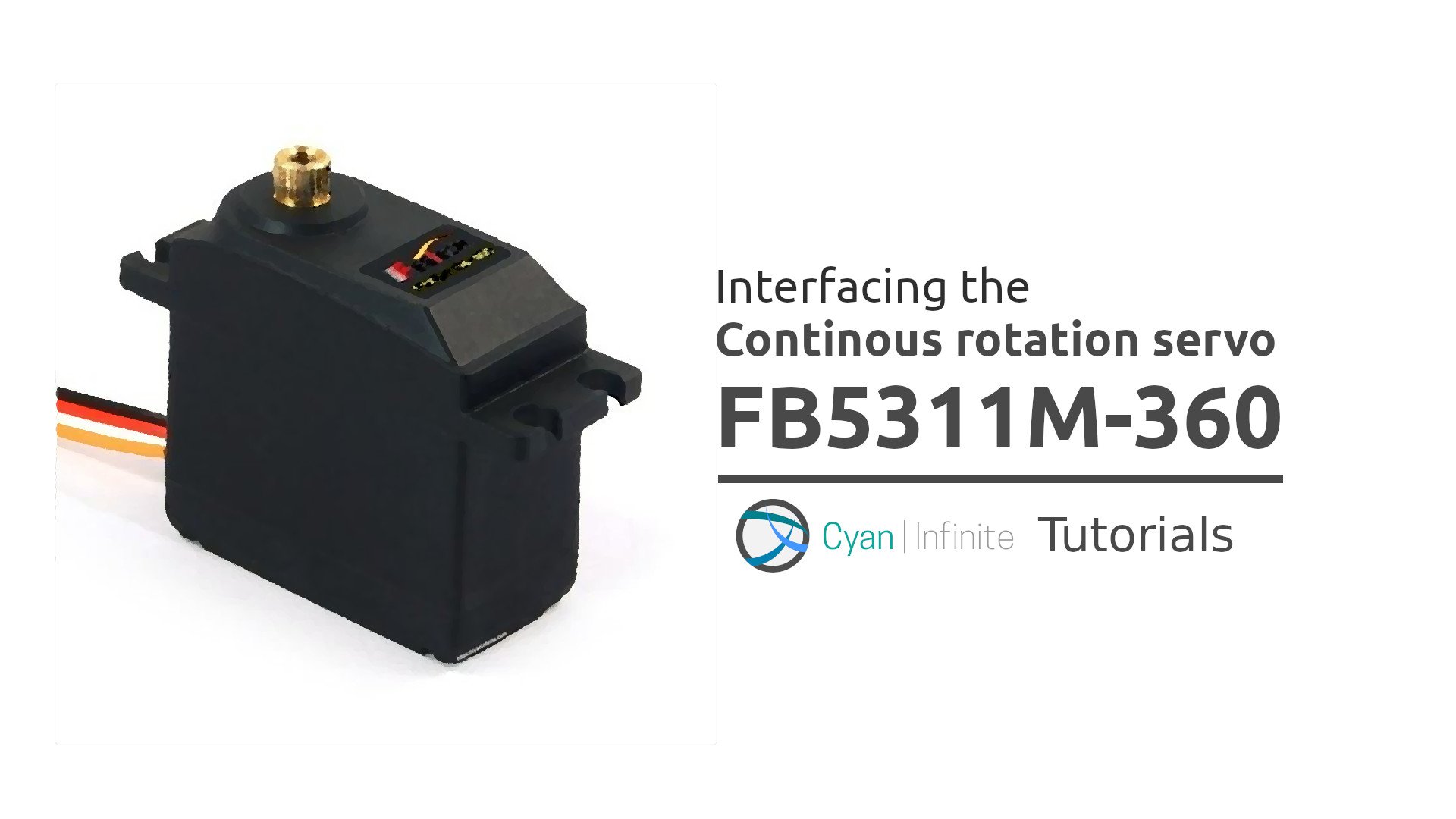
RC Servos are pretty useful in applications that require position (angle) base control, but when speed control is required instead, these RC servos are modified to become continuous rotation servo motors! In this tutorial, the FB5311M-360 Continuous rotation servo would be explored via a few examples, which consists of an extra encoder pin other than the 3 usual pins: VCC, GND, SIG.
Overview
Continuous rotation servo motors allow one to control the speed of the service motor instead of positional control. (Since the internal potentiometer that determines the Servo’s position is removed.) However, the unique feature of this continuous rotation servo is that it has an encoder pin that current position of the servo could be determined, on top of the usual speed control pin commonly found.
Components
| Arduino Uno | x 1 |
| Breadboard (Tiny) | x 1 |
| FB5311M-360 Continuous Rotation Servo Motor | x 1 |
| Jumper Wires | x ~12 |
Schematics
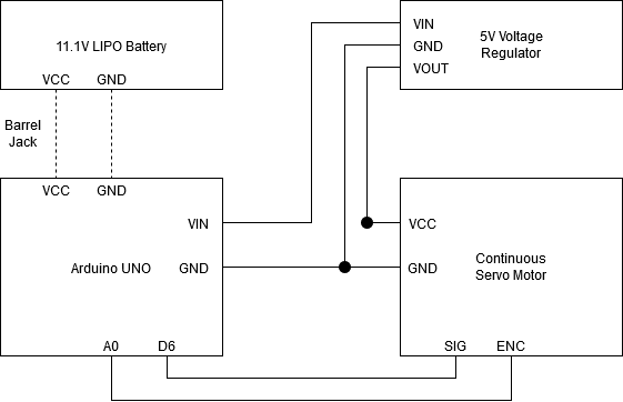
The Arduino Uno would be powered by a 11.1V LiPO battery through the barrel jack adapter. A 5V regulator is used to provide power to the servo as the current draw by the servo may be too high, which may damage the Arduino.
Note: The pins of the schematics would be mapped accordingly to the colour scheme of the servo as shown below:
– Black: GND
– Red: 5V
– White: SIG [Speed Control Signal]
– Orange: ENC [Position Feedback]
Controlling the Servo Motor
The same library which is used to control a servo, Servo.h, would be used to control this servo. Instead of writing the position to the servo, the speed of the servo would be written instead. Writing 90 to the servo would stop the motor, whereas writing > 90 would turn the servo clockwise, and writing less than 90 would turn the motor anti-clockwise.
| Speed | ||
| < 90 | = 90 | > 90 |
| Rotate anti-clockwise | Stop | Rotate clockwise |
Code
In this test, we would be reading the position of the servo via the encoder & moving the servo towards the specified position of the Continuous Rotational Servo FB5311M-360.
What this code does is that the servo would first be initialized and it would get the current encoder position. The current position would be offset by 10 as the current position may be the same as the set point (which is 40). After which, it would proceed into a while loop as long as the current position is not equal to the target position. When the position is below 300, the servo would rotate at around 22% of the maximum speed (40rpm*0.22=~8.8rpm) , else it would be rotating at full speed around 40rpm.
Note: The values of the servo position differs when rotating in different direction!
#include <Servo.h>
#define SRVPIN 6    // Servo pin
#define ENCPIN A0   // Servo motor pin
#define DEBUG 0

#define TARGETPOS 40 // Target encoder position
Servo mservo;
int targetPos{0};
int currentPos{0};

void debugOut(int t) {
  if (DEBUG) {
    Serial.println(t);
  }
}

void setup() {
  if (DEBUG) {
    Serial.begin(115200);
  }
  pinMode(ENCPIN, INPUT);
  mservo.attach(SRVPIN);
  //Stop motor
  mservo.write(90);
  targetPos = analogRead(ENCPIN);
  currentPos = targetPos-10;
  debugOut(targetPos);
  while (currentPos != TARGETPOS) {
    currentPos = analogRead(A0);
    debugOut(currentPos);
    if (currentPos < 300) {
      mservo.write(70);
    } else {
      //Rotate acw at full speed
      mservo.write(0);
    }
  }
  mservo.write(90);
}

void loop() {

}
How do I know write(70) would be 22% of the maximum speed?
The motor would be stationary when we write(90), so taking anti-clockwise as positive, we would subtract the target speed (70) from the stationary speed (90), resulting in a value of 20. To get the percentage, we would take the ratio of the result and the stationary speed: 20/90 = ~22%!
With Hall Effect Sensor
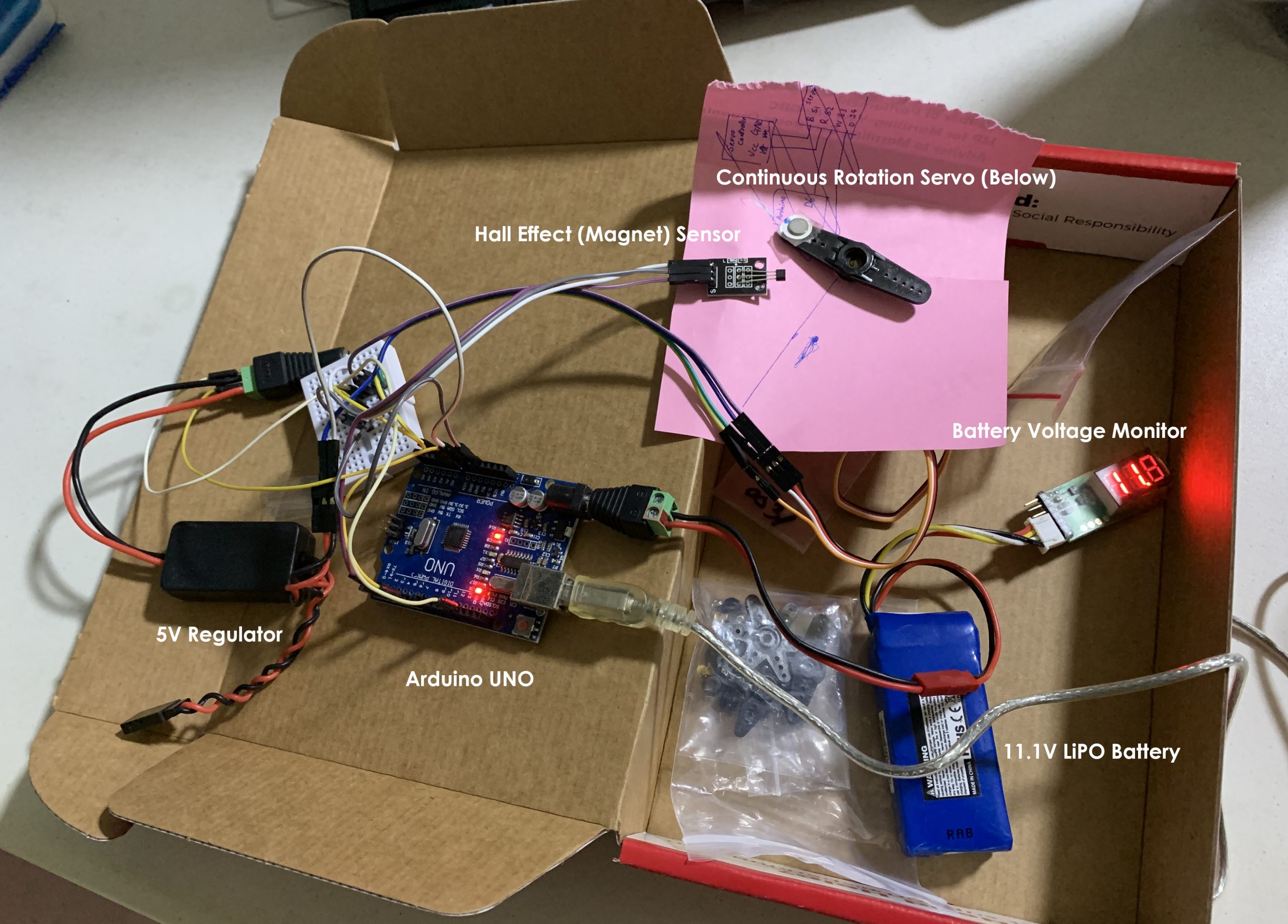
After testing the servo with the encoder, we would move on to add a hall effect sensor to allow the micro controller to be able to “count” the number of rounds the servo has rotated via the transition change of the hall effect sensor (rising edge).
Schematics
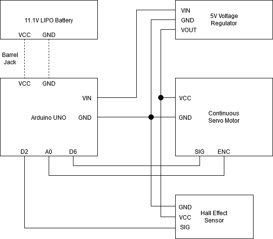
The setup would be similar to the previous setup, the only addition would be the inclusion of a hall sensor with a magnet attached to the servo horn.
Demo
[Coming soon]
Code
Gets position of magnet & RPM of the continuous rotation servo that rotates both clockwise & anti-clockwise direction 3 times.
#include <Servo.h>
#define SRVPIN 6    // Servo pin
#define ENCPIN A0   // Servo motor pin
#define MGTPIN 2    // Hall effect pin
#define ROT_TEST 3 // Get 3 rounds of value

#define DEBUG 1 //Show debug serial

Servo mservo;
int targetPos;
int currentPos;

int currentSpd{0};

//Track count
int count{0};
bool noMagnet{1}; //Get state of Hall Effect sensor, Active Low
bool prevState{1};
bool isFirstValue{1}; //Used to ignore the first reading of each rpm reading

//Test
bool acwTest{1}; //Test acw
bool cwTest{0}; //Test cw

//Timing
unsigned long previousMillis = 0; // will store last time LED was updated
unsigned long oneRound{0};
unsigned long currentMillis;

void getRPM() {
oneRound = currentMillis - previousMillis;
float toSecond = (float)oneRound / 1000;
float rpm = 60 / toSecond;
if (DEBUG) {
if (!isFirstValue) {
/*
Serial.print(oneRound);
Serial.print(",");
Serial.print(toSecond);*/
Serial.print("Position: ");
Serial.print(analogRead(A0));
Serial.print(", RPM: ");
Serial.println(rpm);
} else {
isFirstValue = false; //Print the output in next turn
}
}
}

void pauseMotor(int tm) {
currentSpd = 90;
mservo.write(currentSpd);
delay(tm);
}

//Init
void setup() {
Serial.begin(115200);
//Set output mode
pinMode(ENCPIN, INPUT);
pinMode(MGTPIN, INPUT);
mservo.attach(SRVPIN);
//Ensure servomotor not moving
mservo.write(90);
}

void loop() {
noMagnet = digitalRead(MGTPIN);
currentMillis = millis();

//Check test case
if (acwTest) {
//Rotate anticlockwise
currentSpd = 0;
} else {
//Rotate clockwise
currentSpd = 180;
}

//Check for rising edge
if (!noMagnet) {
if (prevState != noMagnet) {
if (acwTest) {
getRPM();
count++;
} else if (cwTest) {
getRPM();
count--;
}
previousMillis = currentMillis;
}
}
else if (count >= ROT_TEST + 1 && acwTest) //+1 Is to ignore first reading
{
//Start CW test
acwTest = 0;
cwTest = 1;
isFirstValue = true; //Reset since starting new test
pauseMotor(1000);
}
else if (count <= 0 && cwTest) {
//Start ACW test
acwTest = 0;
cwTest = 0;
pauseMotor(1000);
} else if (!acwTest && !cwTest) {
currentSpd = 90;
}
prevState = noMagnet;
mservo.write(currentSpd);
}
Results
After a few test, it was measured that the angular velocity of the servo at 5v was around 40rpm, which was close to the expected value as the datasheet. However, the readings of the encoder was noisy, which resulted in the ocasional overshooting of the target position when it was rotating. Nevertheless, the servo motor would be good enough for application which requires speed control but does not need much accuracy.