
Contents
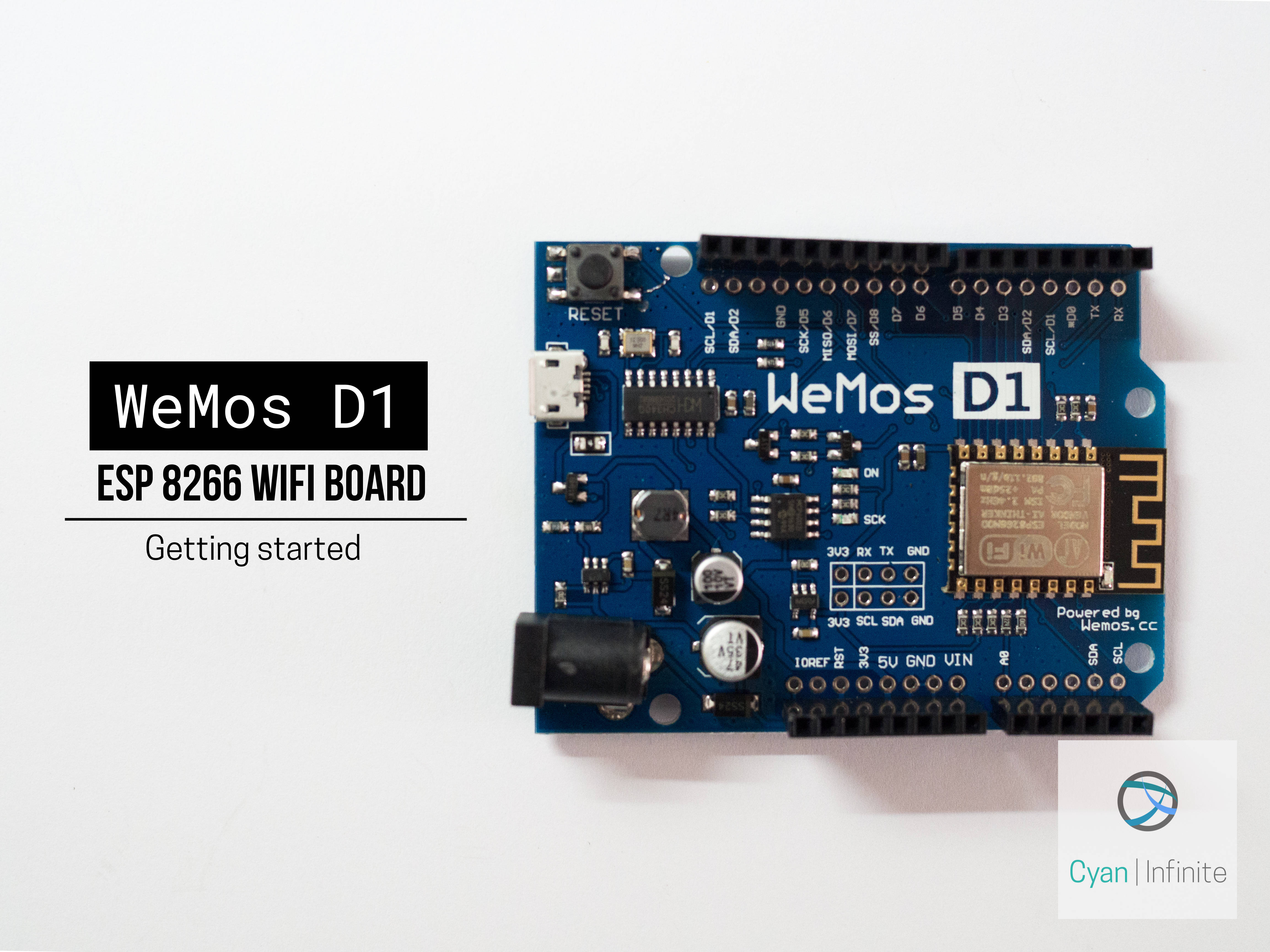
The WeMos D1 is a ESP8266 WiFi based board that uses the Arduino layout with a operating voltage of 3.3V. As the documentation of this board online can be a little confusing, the purpose of this tutorial is to combine and simplify the steps needed to setup this board for development. With that, let’s proceed on with the specifications of the board.
Note: This is NOT an Arduino board, it only uses the Arduino Uno layout for the board design!

Specifications
Here are the specification of the board:
| Microcontroller | ESP-8266EX |
| Operating Voltage | 3.3V |
| Digital I/O Pins | 11 |
| Analog Input Pins | 1 |
| Clock Speed | 80MHz/160MHz |
| Flash | 4M bytes |
| Length | 68.6mm |
| Width | 53.4mm |
| Weight | 25g |
In summary, the board is controlled by the ESP8266 chip (a 32-Bit processor) and has a larger flash memory compared to an Arduino Uno. It consists of 11 digital I/O pins and 1 analogue (input) pin. the board can be connected using a Micro-B type USB cable. (Aka “Android Cable”)
Pinouts
All the I/O pins:
- Runs at 3.3V
- Have interrupt/PWM/I2C/one-wire support except D0
| Pin | Function | ESP-8266 Pin |
| TX | TXD | TXD |
| RX | RXD | RXD |
| A0 | Analog input, max 3.3V input | A0 |
| D0 | IO | GPIO16 |
| D1 | IO, SCL | GPIO5 |
| D2 | IO, SDA | GPIO4 |
| D3 | IO, 10k Pull-up | GPIO0 |
| D4 | IO, 10k Pull-up, BUILTIN_LED | GPIO2 |
| D5 | IO, SCK | GPIO14 |
| D6 | IO, MISO | GPIO12 |
| D7 | IO, MOSI | GPIO13 |
| D8 | IO, 10k Pull-down, SS | GPIO15 |
| G | Ground | GND |
| 5V | 5V | – |
| 3V3 | 3.3V | 3.3V |
| RST | Reset | RST |
IDE
There are 2 IDE that can be used to program the ESP8266:
- The Arduino IDE
- The NodeMCU IDE
In this tutorial, we’ll be looking at how to setup the board with the Arduino IDE on Windows. (For installation on a Linux-based system, you can visit this website, though the installation instructions are very similar: https://www.wemos.cc/tutorial/get-started-arduino.html)
Software Requirements
- CH340G USB to UART driver: https://www.wemos.cc/downloads
- Python 2.7: https://www.python.org/downloads/release/python-2713/
- Arduino 1.8.2: https://www.arduino.cc/en/Main/Software
Installation
Create a new folder esp8266com/esp8266 in your Arduino sketch directory. (The Arduino sketch location should be located in “My Documents > Arduino” by default).

Next, download the library/driver file (as zip) from Github: https://github.com/esp8266/Arduino
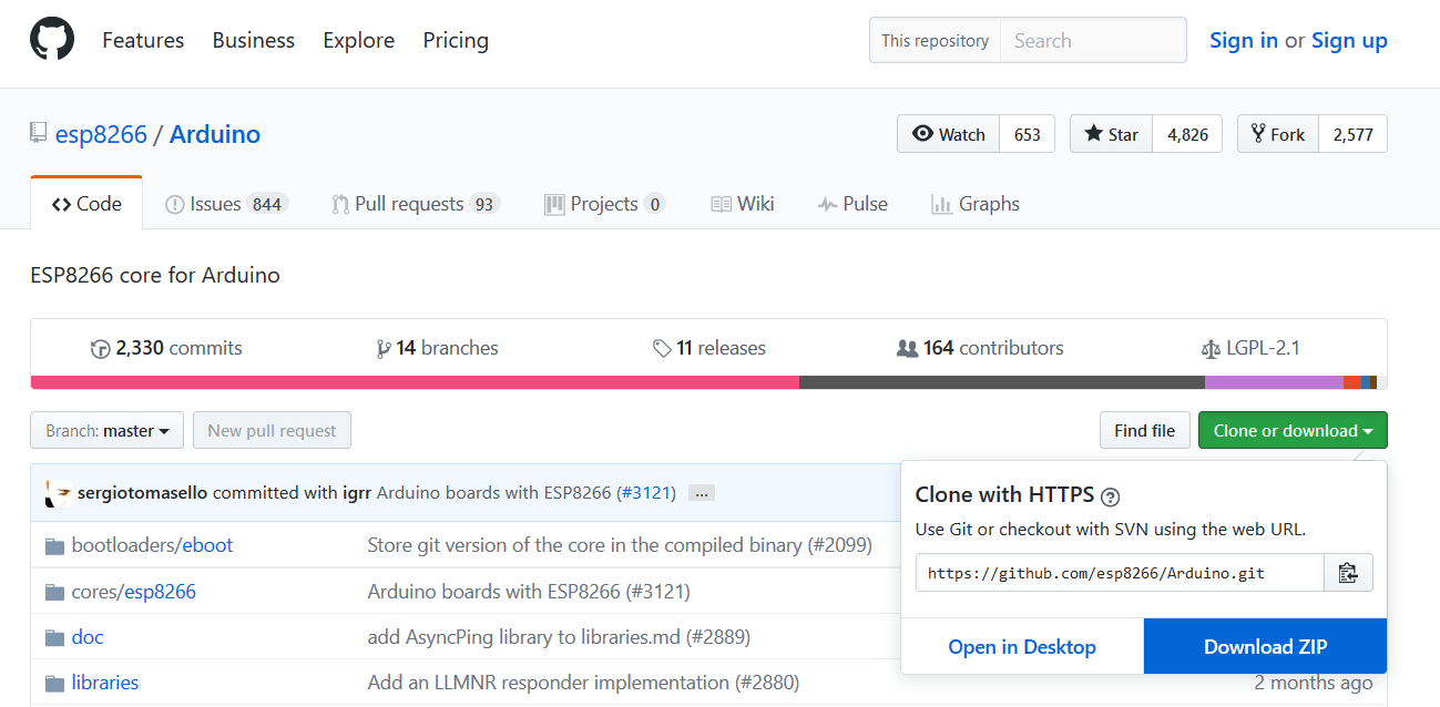
After the download has completed, copy the zip file over to the [Arduino sketch]/hardware/esp8266com/esp8266 directory & extract the contents. A Arduino-Master folder will be created.
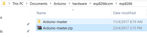
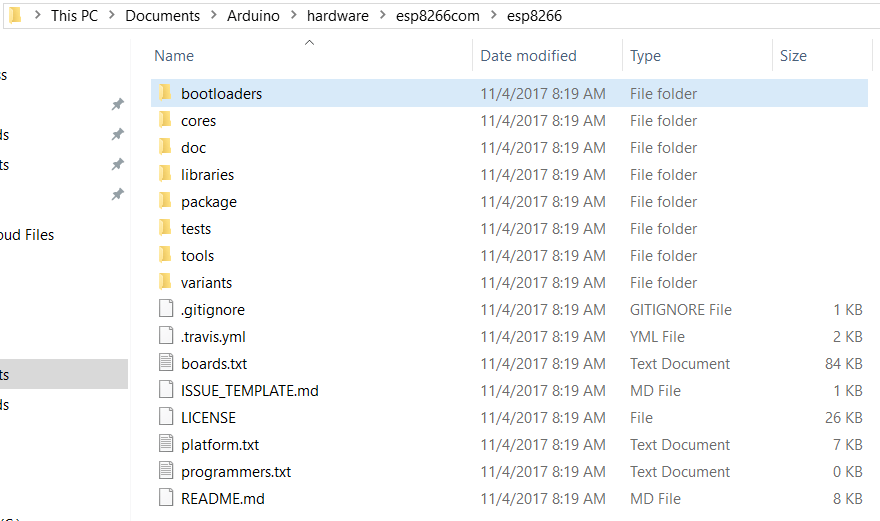
Next, enter the directory and drag all the content into the main directory. Finally, remove both the Arduino-master.zip and the Arduino-master folder. Your directory now should look like this:
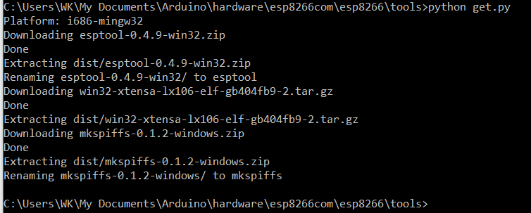
Open the terminal and enter the esp8266/tools folder. (e.g. [Arduino sketch]/hardware/esp8266com/esp8266/tools) After that, exceute the get.py script via the python command.
C:\Users\[username]\My Documents\Arduino\hardware\esp8266com\esp8266\tools> python get.py
This will download the Binary Tools required to program the board. Once the installation has completed, it should look like that:
With that, you are ready to test out your WeMos D1 board!
Examples
Blink
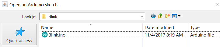
To test out whether the hardware library/driver is properly installed, we’ll be testing out the sample program Blink, an equivalent to the Hello World! example in the Hardware environment. To do so, start the Arduino IDE and open the sketch at the following location:
C:\Users\[username]\Documents\Arduino\hardware\esp8266com\esp8266\libraries\esp8266\examples\Blink
If you are lazy, just copy the code below:
/*
 ESP8266 Blink by Simon Peter
 Blink the blue LED on the ESP-01 module
 This example code is in the public domain

 The blue LED on the ESP-01 module is connected to GPIO1
 (which is also the TXD pin; so we cannot use Serial.print() at the same time)

 Note that this sketch uses LED_BUILTIN to find the pin with the internal LED
*/

void setup() {
  pinMode(LED_BUILTIN, OUTPUT);     // Initialize the LED_BUILTIN pin as an output
}

// the loop function runs over and over again forever
void loop() {
  digitalWrite(LED_BUILTIN, LOW);   // Turn the LED on (Note that LOW is the voltage level
                                    // but actually the LED is on; this is because
                                    // it is active low on the ESP-01)
  delay(1000);                      // Wait for a second
  digitalWrite(LED_BUILTIN, HIGH);  // Turn the LED off by making the voltage HIGH
  delay(2000);                      // Wait for two seconds (to demonstrate the active low LED)
}
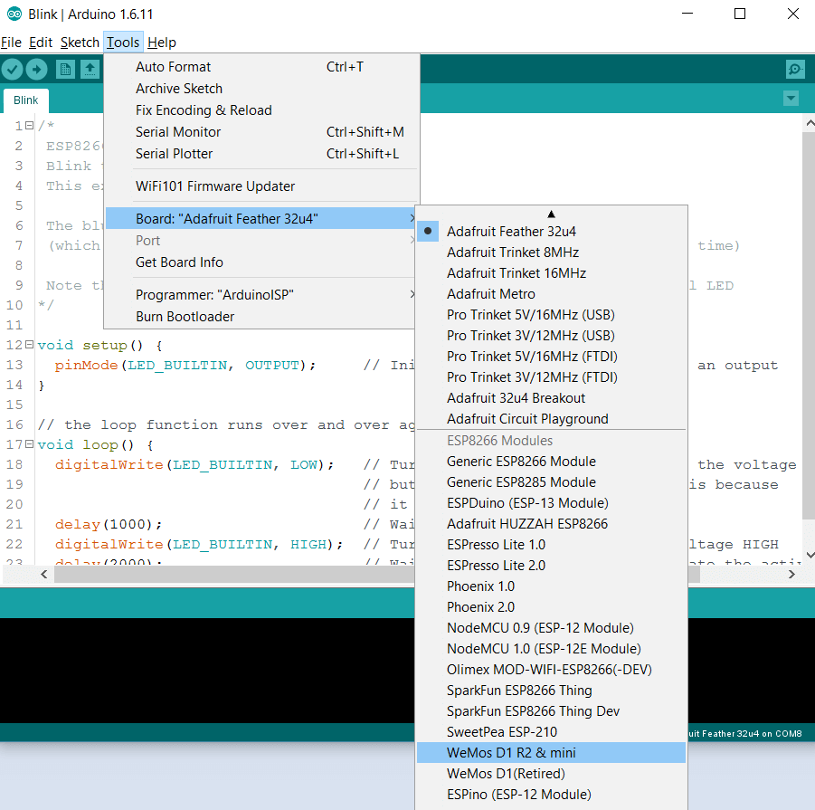
After opening the sketch file, go to Tools > Board and select the “WeMos D1 R2 & Mini” option. Connect the WeMos Board & upload the code. The LED on the ESP8266 will start to blink. (If the LED on the ESP8266 is blinking when a USB is plugged, you can try modifying the “delay” values to see whether it updates accordingly.)
Checking out the Chip ID
To check the ID of the chip, copy the code below & upload into the WeMos D1 board.
/*
 *  Get Chip ID
 */

void setup() {
  Serial.begin(115200);
}

void loop() {
  Serial.println("");
  Serial.println("");
  Serial.println("Check ID in:");
  Serial.println("https://www.wemos.cc/verify_products");
  Serial.printf("Chip ID = %08Xn", ESP.getChipId());
  Serial.println("");
  Serial.println("");
  delay(5000);
}
After the code has been uploaded, open up the Serial Monitor and set the baudrate to 115200. The ID should be printed in the monitor.
Running a Simple Web Server
For this section, the ESP8266 will be ran as a simple server in a local network, hosting a simple HTML file at port 80. Go to the following directory & open up HelloServer.ino.
C:\Users\[username]\Documents\Arduino\hardware\esp8266com\esp8266\libraries\ESP8266WebServerexamples\HelloServer
Alternatively, you can copy the code below:
#include <ESP8266WiFi.h>
#include <WiFiClient.h>
#include <ESP8266WebServer.h>
#include <ESP8266mDNS.h>

const char* ssid = "........";
const char* password = "........";

ESP8266WebServer server(80);

const int led = 13;

void handleRoot() {
digitalWrite(led, 1);
server.send(200, "text/plain", "Hello from esp8266!");
digitalWrite(led, 0);
}

void handleNotFound(){
digitalWrite(led, 1);
String message = "File Not Foundnn";
message += "URI: ";
message += server.uri();
message += "nMethod: ";
message += (server.method() == HTTP_GET)?"GET":"POST";
message += "nArguments: ";
message += server.args();
message += "n";
for (uint8_t i=0; i<server.args(); i++){
message += " " + server.argName(i) + ": " + server.arg(i) + "n";
}
server.send(404, "text/plain", message);
digitalWrite(led, 0);
}

void setup(void){
pinMode(led, OUTPUT);
digitalWrite(led, 0);
Serial.begin(115200);
WiFi.begin(ssid, password);
Serial.println("");

// Wait for connection
while (WiFi.status() != WL_CONNECTED) {
delay(500);
Serial.print(".");
}
Serial.println("");
Serial.print("Connected to ");
Serial.println(ssid);
Serial.print("IP address: ");
Serial.println(WiFi.localIP());

if (MDNS.begin("esp8266")) {
Serial.println("MDNS responder started");
}

server.on("/", handleRoot);

server.on("/inline", [](){
server.send(200, "text/plain", "this works as well");
});

server.onNotFound(handleNotFound);

server.begin();
Serial.println("HTTP server started");
}

void loop(void){
server.handleClient();
}
Before uploading the code, you have to change 2 variable value: ssid and password. Replace them with your router’s ssid (or connection name) and the password accordingly. For example, if the router name is “router-17” and password “1234”, the variables would look something like this:
const char* ssid = "router-17";
const char* password = "1234";
After changing the variable values, upload the code and open up the Serial Monitor. (Set the baud rate to 115200) If the board is connected to the network, it will display it’s IP address. Assuming that your computer is connected to the same network, copy the IP address of the server and paste it over at your preferred web browser. The webpage would display a simple “Hello from esp8266!” webpage.
References/Resources
- https://www.wemos.cc/product/d1.html
- https://github.com/wemos/D1_mini_Examples/blob/master/examples/02.Special/GetChipID/GetChipID.ino
- http://educ8s.tv/arduino-esp8266-tutorial-first-look-at-the-wemos-d1-arduino-compatible-esp8266-wifi-board/
Hi,
is the circuit can be used to control any electrical appliance by connecting IO PINS
Hi, the GPIO pins on the board could be used, but take note that it only accepts and outputs a maximum of only 3.3V.
what range of voltages can be applied at the barrel connector on this board?
Hi, the board could accept a range of 9-24V power input.
More info could be found here: https://wiki.wemos.cc/products:d1:d1
I am trying to use this board to read RF 433 MHz sensor values. I need to know which pin corresponds to interrupt pin 0, to be able to use the supplied code. Do you know which pin it would be?
https://github.com/sui77/rc-switch/wiki/HowTo_Receive
Hi Akash,
Interrupts could be attached in any GPIOs of the ESP8266: https://github.com/esp8266/Arduino/blob/master/doc/reference.rst#interrupts
Instructions to install were excellent. Was able to get demos going quickly.
Thank you.
Excellent instructions. Thank You. This was the fastest I ever got a board working like it should and some positive results to boot.
Many thanks for the great articles. Been viewing with my son as i teach him basics of microcontollers.
“C:\Users\[username]\My Documents\Arduino\hardware\esp8266com\esp8266\tools> python get.py” no longer works since the “python get.py” was renamed to “get.py”. You can either run the command in cmd “C:\Users\[username]\My Documents\Arduino\hardware\esp8266com\esp8266\tools> get.py” or run the “get.py” manually from “Documents\Arduino\esp8266com\esp8266\tools” folder.
Thanks for helping me get my board up and running. Although in the web server example code there are a bunch of empty #includes. What exactly are we including here?
Hi Brett, the include section was to import the libraries which was not showing up, have rectified the issue and should be showing now.
Thank you for this tutorial!