Contents
Time to interface a 0.96" graphical OLED I2C Display with a Arduino Uno! This tiny OLED Display is useful in displaying various data from sensors, graphics and many more. In this tutorial, I’ll be showing you how you can use 2 different libraries to interface a I2C OLED Display with the Arduino Uno, therefore you have an option to choose either 1 of the library to use.

Libraries
There are 2 libraries for available for interfacing the OLED Display, which is:
The tutorial will be split into two parts, starting with the Adafruit graphics library, followed by the U8glib library.
We express our utmost gratitude to Adafruit & u8glib for making their Graphic Libraries Open Source and available!Components
- Arduino Uno x 1
- 0.96″ I2C OLED Display x 1
- Jumper Wires x 4
- Breadboard x 1
Adafuit Library: ssd1306 & GFX library
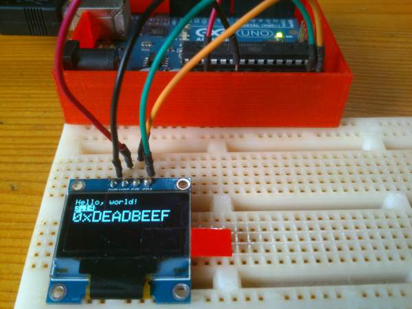
![]()
Demo
Steps
1) Download the following libraries below. Both libraries are required to interface the Arduino to the OLED Display.
2) Extract the Adafruit_SSD1306-master.zip. Rename the extracted folder to Adafruit_SSD1306. Place the Adafruit_SSD1306 folder inside your <arduinosketchfolder>/libraries/ folder. (Which is most likely found in "My Documents/Arduino"). If there is no such folder, create one.
3) Repeat step 2 for the Adafruit GFX library.
4) Wire the arduino as shown below. Please note that if you are using an revision 3 Arduino Uno board, you have 2 options: wire it at the analog input area or the pins beside the AREF pin. For UNO boards that are before revision 3, you can only wire it one way: which is at the analog input area. For the power supply of the Display, you can either power it at 5V or 3.3V.
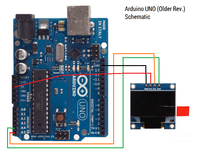 |
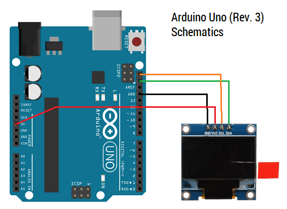 |
Why wire the SDA and SCL to (Analog pin) A4 & A5? Since the Adafruit library uses the Wire Library, the pins for the SDA & SCL pins are defined to be at A4 & A5 for I2C communication. For more information about the Wire library, visit: http://arduino.cc/en/reference/wire.
5) Start the Arduino IDE. Select File>Examples>Adafruit_SSD1306>"ssd1206_128x64_i2c". I would be using the Adafruit sample code with a minor tweak, since the address of my OLED Display is different from the one used in their sample code.
Therefore, change the address from 0x3D to 0x3C before uploading the code onto the Arduino board. Alternatively, you can copy the code below. Upload the code.
/*********************************************************************
This is an example for our Monochrome OLEDs based on SSD1306 drivers

  Pick one up today in the adafruit shop!
  ------> http://www.adafruit.com/category/63_98

This example is for a 128x64 size display using I2C to communicate
3 pins are required to interface (2 I2C and one reset)

Adafruit invests time and resources providing this open source code,
please support Adafruit and open-source hardware by purchasing
products from Adafruit!

Written by Limor Fried/Ladyada  for Adafruit Industries.
BSD license, check license.txt for more information
All text above, and the splash screen must be included in any redistribution
*********************************************************************/

#include <SPI.h>
#include <Wire.h>
#include <Adafruit_GFX.h>
#include <Adafruit_SSD1306.h>

#define OLED_RESET 4
Adafruit_SSD1306 display(OLED_RESET);

#define NUMFLAKES 10
#define XPOS 0
#define YPOS 1
#define DELTAY 2

#define LOGO16_GLCD_HEIGHT 16
#define LOGO16_GLCD_WIDTH  16
static const unsigned char PROGMEM logo16_glcd_bmp[] =
{ B00000000, B11000000,
  B00000001, B11000000,
  B00000001, B11000000,
  B00000011, B11100000,
  B11110011, B11100000,
  B11111110, B11111000,
  B01111110, B11111111,
  B00110011, B10011111,
  B00011111, B11111100,
  B00001101, B01110000,
  B00011011, B10100000,
  B00111111, B11100000,
  B00111111, B11110000,
  B01111100, B11110000,
  B01110000, B01110000,
  B00000000, B00110000 };

#if (SSD1306_LCDHEIGHT != 64)
#error("Height incorrect, please fix Adafruit_SSD1306.h!");
#endif

void setup()   {
  Serial.begin(9600);

  // by default, we'll generate the high voltage from the 3.3v line internally! (neat!)
  display.begin(SSD1306_SWITCHCAPVCC, 0x3C);  // initialize with the I2C addr 0x3D (for the 128x64). Change address from 0x3D to 0x3C
  // init done

  // Show image buffer on the display hardware.
  // Since the buffer is intialized with an Adafruit splashscreen
  // internally, this will display the splashscreen.
  display.display();
  delay(2000);

  // Clear the buffer.
  display.clearDisplay();

  // draw a single pixel
  display.drawPixel(10, 10, WHITE);
  // Show the display buffer on the hardware.
  // NOTE: You _must_ call display after making any drawing commands
  // to make them visible on the display hardware!
  display.display();
  delay(2000);
  display.clearDisplay();

  // draw many lines
  testdrawline();
  display.display();
  delay(2000);
  display.clearDisplay();

  // draw rectangles
  testdrawrect();
  display.display();
  delay(2000);
  display.clearDisplay();

  // draw multiple rectangles
  testfillrect();
  display.display();
  delay(2000);
  display.clearDisplay();

  // draw mulitple circles
  testdrawcircle();
  display.display();
  delay(2000);
  display.clearDisplay();

  // draw a white circle, 10 pixel radius
  display.fillCircle(display.width()/2, display.height()/2, 10, WHITE);
  display.display();
  delay(2000);
  display.clearDisplay();

  testdrawroundrect();
  delay(2000);
  display.clearDisplay();

  testfillroundrect();
  delay(2000);
  display.clearDisplay();

  testdrawtriangle();
  delay(2000);
  display.clearDisplay();

  testfilltriangle();
  delay(2000);
  display.clearDisplay();

  // draw the first ~12 characters in the font
  testdrawchar();
  display.display();
  delay(2000);
  display.clearDisplay();

  // draw scrolling text
  testscrolltext();
  delay(2000);
  display.clearDisplay();

  // text display tests
  display.setTextSize(1);
  display.setTextColor(WHITE);
  display.setCursor(0,0);
  display.println("Hello, world!");
  display.setTextColor(BLACK, WHITE); // 'inverted' text
  display.println(3.141592);
  display.setTextSize(2);
  display.setTextColor(WHITE);
  display.print("0x"); display.println(0xDEADBEEF, HEX);
  display.display();
  delay(2000);

  // miniature bitmap display
  display.clearDisplay();
  display.drawBitmap(30, 16,  logo16_glcd_bmp, 16, 16, 1);
  display.display();

  // invert the display
  display.invertDisplay(true);
  delay(1000);
  display.invertDisplay(false);
  delay(1000);

  // draw a bitmap icon and 'animate' movement
  testdrawbitmap(logo16_glcd_bmp, LOGO16_GLCD_HEIGHT, LOGO16_GLCD_WIDTH);
}

void loop() {

}

void testdrawbitmap(const uint8_t *bitmap, uint8_t w, uint8_t h) {
  uint8_t icons[NUMFLAKES][3];

  // initialize
  for (uint8_t f=0; f< NUMFLAKES; f++) {
    icons[f][XPOS] = random(display.width());
    icons[f][YPOS] = 0;
    icons[f][DELTAY] = random(5) + 1;

    Serial.print("x: ");
    Serial.print(icons[f][XPOS], DEC);
    Serial.print(" y: ");
    Serial.print(icons[f][YPOS], DEC);
    Serial.print(" dy: ");
    Serial.println(icons[f][DELTAY], DEC);
  }

  while (1) {
    // draw each icon
    for (uint8_t f=0; f< NUMFLAKES; f++) {
      display.drawBitmap(icons[f][XPOS], icons[f][YPOS], logo16_glcd_bmp, w, h, WHITE);
    }
    display.display();
    delay(200);

    // then erase it + move it
    for (uint8_t f=0; f< NUMFLAKES; f++) {
      display.drawBitmap(icons[f][XPOS], icons[f][YPOS],  logo16_glcd_bmp, w, h, BLACK);
      // move it
      icons[f][YPOS] += icons[f][DELTAY];
      // if its gone, reinit
      if (icons[f][YPOS] > display.height()) {
    icons[f][XPOS] = random(display.width());
    icons[f][YPOS] = 0;
    icons[f][DELTAY] = random(5) + 1;
      }
    }
   }
}

void testdrawchar(void) {
  display.setTextSize(1);
  display.setTextColor(WHITE);
  display.setCursor(0,0);

  for (uint8_t i=0; i < 168; i++) {
    if (i == 'n') continue;
    display.write(i);
    if ((i > 0) && (i % 21 == 0))
      display.println();
  }
  display.display();
}

void testdrawcircle(void) {
  for (int16_t i=0; i<display.height(); i+=2) {
    display.drawCircle(display.width()/2, display.height()/2, i, WHITE);
    display.display();
  }
}

void testfillrect(void) {
  uint8_t color = 1;
  for (int16_t i=0; i<display.height()/2; i+=3) {
    // alternate colors
    display.fillRect(i, i, display.width()-i*2, display.height()-i*2, color%2);
    display.display();
    color++;
  }
}

void testdrawtriangle(void) {
  for (int16_t i=0; i<min(display.width(),display.height())/2; i+=5) {
    display.drawTriangle(display.width()/2, display.height()/2-i,
                     display.width()/2-i, display.height()/2+i,
                     display.width()/2+i, display.height()/2+i, WHITE);
    display.display();
  }
}

void testfilltriangle(void) {
  uint8_t color = WHITE;
  for (int16_t i=min(display.width(),display.height())/2; i>0; i-=5) {
    display.fillTriangle(display.width()/2, display.height()/2-i,
                     display.width()/2-i, display.height()/2+i,
                     display.width()/2+i, display.height()/2+i, WHITE);
    if (color == WHITE) color = BLACK;
    else color = WHITE;
    display.display();
  }
}

void testdrawroundrect(void) {
  for (int16_t i=0; i<display.height()/2-2; i+=2) {
    display.drawRoundRect(i, i, display.width()-2*i, display.height()-2*i, display.height()/4, WHITE);
    display.display();
  }
}

void testfillroundrect(void) {
  uint8_t color = WHITE;
  for (int16_t i=0; i<display.height()/2-2; i+=2) {
    display.fillRoundRect(i, i, display.width()-2*i, display.height()-2*i, display.height()/4, color);
    if (color == WHITE) color = BLACK;
    else color = WHITE;
    display.display();
  }
}

void testdrawrect(void) {
  for (int16_t i=0; i<display.height()/2; i+=2) {
    display.drawRect(i, i, display.width()-2*i, display.height()-2*i, WHITE);
    display.display();
  }
}

void testdrawline() {
  for (int16_t i=0; i<display.width(); i+=4) {
    display.drawLine(0, 0, i, display.height()-1, WHITE);
    display.display();
  }
  for (int16_t i=0; i<display.height(); i+=4) {
    display.drawLine(0, 0, display.width()-1, i, WHITE);
    display.display();
  }
  delay(250);

  display.clearDisplay();
  for (int16_t i=0; i<display.width(); i+=4) {
    display.drawLine(0, display.height()-1, i, 0, WHITE);
    display.display();
  }
  for (int16_t i=display.height()-1; i>=0; i-=4) {
    display.drawLine(0, display.height()-1, display.width()-1, i, WHITE);
    display.display();
  }
  delay(250);

  display.clearDisplay();
  for (int16_t i=display.width()-1; i>=0; i-=4) {
    display.drawLine(display.width()-1, display.height()-1, i, 0, WHITE);
    display.display();
  }
  for (int16_t i=display.height()-1; i>=0; i-=4) {
    display.drawLine(display.width()-1, display.height()-1, 0, i, WHITE);
    display.display();
  }
  delay(250);

  display.clearDisplay();
  for (int16_t i=0; i<display.height(); i+=4) {
    display.drawLine(display.width()-1, 0, 0, i, WHITE);
    display.display();
  }
  for (int16_t i=0; i<display.width(); i+=4) {
    display.drawLine(display.width()-1, 0, i, display.height()-1, WHITE);
    display.display();
  }
  delay(250);
}

void testscrolltext(void) {
  display.setTextSize(2);
  display.setTextColor(WHITE);
  display.setCursor(10,0);
  display.clearDisplay();
  display.println("scroll");
  display.display();

  display.startscrollright(0x00, 0x0F);
  delay(2000);
  display.stopscroll();
  delay(1000);
  display.startscrollleft(0x00, 0x0F);
  delay(2000);
  display.stopscroll();
  delay(1000);
  display.startscrolldiagright(0x00, 0x07);
  delay(2000);
  display.startscrolldiagleft(0x00, 0x07);
  delay(2000);
  display.stopscroll();
}
u8glib Library
Universal Graphics Library for 8 Bit Embedded Systems

Demo
Steps
1) Download the u8glib library from https://code.google.com/p/u8glib/. Download the "Arduino" version.
2) Extract the zipfile (e.g u8glib_arduino_v1.16.zip). Rename the extracted file as "u8glib". Place the "u8glib" folder inside your <arduinosketchfolder>/libraries/ folder. (Which is most likely found in "My Documents/Arduino"). If there is no such folder, create one.
3) Wire the arduino as shown below. Please note that if you are using an revision 3 Arduino Uno board, you have 2 options: wire it at the analog input area or the pins beside the AREF pin. For UNO boards that are before revision 3, you can only wire it one way: which is at the analog input area. For the power supply of the Display, you can either power it at 5V or 3.3V.
|
|
Why wire the SDA and SCL to (Analog pin) A4 & A5? Since the Adafruit library uses the Wire Library, the pins for the SDA & SCL pins are defined to be at A4 & A5 for I2C communication. For more information about the Wire library, visit: http://arduino.cc/en/reference/wire.
4) Start the Arduino IDE. Select File>Examples>U8glib>"GraphicsTest". Uncomment the "U8GLIB_SSD1306_128X64 u8g(U8G_I2C_OPT_NONE);" code. (Which is located at line 88). Alternatively, you can copy the code below. Upload the code.
/*

  GraphicsTest.pde

  >>> Before compiling: Please remove comment from the constructor of the
  >>> connected graphics display (see below).

  Universal 8bit Graphics Library, http://code.google.com/p/u8glib/

  Copyright (c) 2012, [email protected]
  All rights reserved.

  Redistribution and use in source and binary forms, with or without modification,
  are permitted provided that the following conditions are met:

  * Redistributions of source code must retain the above copyright notice, this list
    of conditions and the following disclaimer.

  * Redistributions in binary form must reproduce the above copyright notice, this
    list of conditions and the following disclaimer in the documentation and/or other
    materials provided with the distribution.

  THIS SOFTWARE IS PROVIDED BY THE COPYRIGHT HOLDERS AND
  CONTRIBUTORS "AS IS" AND ANY EXPRESS OR IMPLIED WARRANTIES,
  INCLUDING, BUT NOT LIMITED TO, THE IMPLIED WARRANTIES OF
  MERCHANTABILITY AND FITNESS FOR A PARTICULAR PURPOSE ARE
  DISCLAIMED. IN NO EVENT SHALL THE COPYRIGHT HOLDER OR
  CONTRIBUTORS BE LIABLE FOR ANY DIRECT, INDIRECT, INCIDENTAL,
  SPECIAL, EXEMPLARY, OR CONSEQUENTIAL DAMAGES (INCLUDING, BUT
  NOT LIMITED TO, PROCUREMENT OF SUBSTITUTE GOODS OR SERVICES;
  LOSS OF USE, DATA, OR PROFITS; OR BUSINESS INTERRUPTION) HOWEVER
  CAUSED AND ON ANY THEORY OF LIABILITY, WHETHER IN CONTRACT,
  STRICT LIABILITY, OR TORT (INCLUDING NEGLIGENCE OR OTHERWISE)
  ARISING IN ANY WAY OUT OF THE USE OF THIS SOFTWARE, EVEN IF
  ADVISED OF THE POSSIBILITY OF SUCH DAMAGE.

*/

#include "U8glib.h"

// setup u8g object
// The complete list of supported
// devices with all constructor calls is here: http://code.google.com/p/u8glib/wiki/device

U8GLIB_SSD1306_128X64 u8g(U8G_I2C_OPT_NONE);    // I2C / TWI

void u8g_prepare(void) {
  u8g.setFont(u8g_font_6x10);
  u8g.setFontRefHeightExtendedText();
  u8g.setDefaultForegroundColor();
  u8g.setFontPosTop();
}

void u8g_box_frame(uint8_t a) {
  u8g.drawStr( 0, 0, "drawBox");
  u8g.drawBox(5,10,20,10);
  u8g.drawBox(10+a,15,30,7);
  u8g.drawStr( 0, 30, "drawFrame");
  u8g.drawFrame(5,10+30,20,10);
  u8g.drawFrame(10+a,15+30,30,7);
}

void u8g_disc_circle(uint8_t a) {
  u8g.drawStr( 0, 0, "drawDisc");
  u8g.drawDisc(10,18,9);
  u8g.drawDisc(24+a,16,7);
  u8g.drawStr( 0, 30, "drawCircle");
  u8g.drawCircle(10,18+30,9);
  u8g.drawCircle(24+a,16+30,7);
}

void u8g_r_frame(uint8_t a) {
  u8g.drawStr( 0, 0, "drawRFrame/Box");
  u8g.drawRFrame(5, 10,40,30, a+1);
  u8g.drawRBox(50, 10,25,40, a+1);
}

void u8g_string(uint8_t a) {
  u8g.drawStr(30+a,31, " 0");
  u8g.drawStr90(30,31+a, " 90");
  u8g.drawStr180(30-a,31, " 180");
  u8g.drawStr270(30,31-a, " 270");
}

void u8g_line(uint8_t a) {
  u8g.drawStr( 0, 0, "drawLine");
  u8g.drawLine(7+a, 10, 40, 55);
  u8g.drawLine(7+a*2, 10, 60, 55);
  u8g.drawLine(7+a*3, 10, 80, 55);
  u8g.drawLine(7+a*4, 10, 100, 55);
}

void u8g_triangle(uint8_t a) {
  uint16_t offset = a;
  u8g.drawStr( 0, 0, "drawTriangle");
  u8g.drawTriangle(14,7, 45,30, 10,40);
  u8g.drawTriangle(14+offset,7-offset, 45+offset,30-offset, 57+offset,10-offset);
  u8g.drawTriangle(57+offset*2,10, 45+offset*2,30, 86+offset*2,53);
  u8g.drawTriangle(10+offset,40+offset, 45+offset,30+offset, 86+offset,53+offset);
}

void u8g_ascii_1() {
  char s[2] = " ";
  uint8_t x, y;
  u8g.drawStr( 0, 0, "ASCII page 1");
  for( y = 0; y < 6; y++ ) {
    for( x = 0; x < 16; x++ ) {
      s[0] = y*16 + x + 32;
      u8g.drawStr(x*7, y*10+10, s);
    }
  }
}

void u8g_ascii_2() {
  char s[2] = " ";
  uint8_t x, y;
  u8g.drawStr( 0, 0, "ASCII page 2");
  for( y = 0; y < 6; y++ ) {
    for( x = 0; x < 16; x++ ) {
      s[0] = y*16 + x + 160;
      u8g.drawStr(x*7, y*10+10, s);
    }
  }
}

void u8g_extra_page(uint8_t a)
{
  if ( u8g.getMode() == U8G_MODE_HICOLOR || u8g.getMode() == U8G_MODE_R3G3B2) {
    /* draw background (area is 128x128) */
    u8g_uint_t r, g, b;
    b = a << 5;
    for( g = 0; g < 64; g++ )
    {
      for( r = 0; r < 64; r++ )
      {
    u8g.setRGB(r<<2, g<<2, b );
    u8g.drawPixel(g, r);
      }
    }
    u8g.setRGB(255,255,255);
    u8g.drawStr( 66, 0, "Color Page");
  }
  else if ( u8g.getMode() == U8G_MODE_GRAY2BIT )
  {
    u8g.drawStr( 66, 0, "Gray Level");
    u8g.setColorIndex(1);
    u8g.drawBox(0, 4, 64, 32);
    u8g.drawBox(70, 20, 4, 12);
    u8g.setColorIndex(2);
    u8g.drawBox(0+1*a, 4+1*a, 64-2*a, 32-2*a);
    u8g.drawBox(74, 20, 4, 12);
    u8g.setColorIndex(3);
    u8g.drawBox(0+2*a, 4+2*a, 64-4*a, 32-4*a);
    u8g.drawBox(78, 20, 4, 12);
  }
  else
  {
    u8g.drawStr( 0, 12, "setScale2x2");
    u8g.setScale2x2();
    u8g.drawStr( 0, 6+a, "setScale2x2");
    u8g.undoScale();
  }
}

uint8_t draw_state = 0;

void draw(void) {
  u8g_prepare();
  switch(draw_state >> 3) {
    case 0: u8g_box_frame(draw_state&7); break;
    case 1: u8g_disc_circle(draw_state&7); break;
    case 2: u8g_r_frame(draw_state&7); break;
    case 3: u8g_string(draw_state&7); break;
    case 4: u8g_line(draw_state&7); break;
    case 5: u8g_triangle(draw_state&7); break;
    case 6: u8g_ascii_1(); break;
    case 7: u8g_ascii_2(); break;
    case 8: u8g_extra_page(draw_state&7); break;
  }
}

void setup(void) {

  // flip screen, if required
  //u8g.setRot180();

  pinMode(13, OUTPUT);
  digitalWrite(13, HIGH);
}

void loop(void) {

  // picture loop
  u8g.firstPage();
  do {
    draw();
  } while( u8g.nextPage() );

  // increase the state
  draw_state++;
  if ( draw_state >= 9*8 )
    draw_state = 0;

  // rebuild the picture after some delay
  delay(150);

}
Displaying Bitmap Image
If you want to display any image onto the OLED Display, you can use the following software to do so:
[ddownload id="774"]
The software is to convert a bitmap image into a binary image. (Meaning your image will become 1s & 0s)
Steps
- Extract the file. Open lcd-bitmap-converter-mono.exe.
- Go to Edit > Options in the menu bar. Select the Image & Font XSLT files in (File Directory)/Xslt respectively. These files should be in *.xslt format. Exit the Options Dialog.
- To convert an image, the image have to be in BMP format and in the dimension of the screen (128×64). To do so, go to File > New Image. A new tab should appear. Click on import… & select the BMP Image.
- Another dialog will appear. Adjust the slider in the centre to adjust the contrast of the output binary image. The left side is the original picture, the right side will be the output image that you will see in the display.
- To export the binary file, go to Edit > Convert… and save the file as a txt file (meaning add a .txt behind the file name!).
- Open the txt file in the location you have saved in any word editor. (I would recommend Notepad++) Scroll down the file till you find a line like “b_00000000”. Copy until you see ‘ }; ‘.

- Open the Adafruit example code. Paste the code into “static const unsigned char PROGMEM logo16_glcd_bmp[]”. You can rename it to anything you want. Used the following code to display the image:
 display.drawBitmap(30, 16,  IMG_NAME_HERE, 16, 16, 1);
 display.display();
- And viola! Your image should appear when you call it.
Troubleshooting
#error ("Height incorrect, please fix Adafruit_SSD1306.h!") – Adafruit
If you have this error, this means that the selected size of the screen in the header file is wrong.
Open up Adafruit_SSD1306.h and scroll to the display definition line. You might see somthing like this:
...
 -----------------------------------------------------------------------*/
//   #define SSD1306_128_64
   #define SSD1306_128_32
//   #define SSD1306_96_16
/*=========================================================================*/
...
As you can see, the display file resolution was set to 12832, but what we want is 12864. (The size of our display!) Therefore, we will uncomment the #define SSD1306_128_64 & comment out #define SSD1306_128_32.
...
 -----------------------------------------------------------------------*/
   #define SSD1306_128_64
//   #define SSD1306_128_32
//   #define SSD1306_96_16
/*=========================================================================*/
...
I want to interface the OLED Display (0.96) Inches 4 pin display and i connected with arduino uno with example code I don’t know to how to allocate address in particular place ibn oled display can anybody provide the solution about this code Thankyou
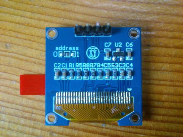
Hi, the I2C address of the display may vary, which could be determined at the back of the display.
Alternatively, you may want to utilise a I2C device scanner sketch to determine the I2C address of the display: https://playground.arduino.cc/Main/I2cScanner/
After that, replace the address obtained from the scan in the sample code provided in the post. Hope this helps!