Contents
You may have seen light chasers in shopping malls, exhibitions, shop displays and many more places, with one light turning on and off after another. In this tutorial, we’ll be looking at creating a simple light chaser with an Arduino Uno, which would take less than an hour to complete. With that, let’s proceed onto creating one!
Side Note
The following posts were merged:
- Simple LED light chaser (19 March 2014)
- LED light chaser using 74HC595 Shift Register & Potentiometer (29 March 2014)
Basic LED light chaser
Published: 19 March 2014, Updated: 03 September 2019
In this tutorial, you will learn how to setup and create a simple light chaser, which will consist of only 3 LEDs. What is a lightchaser? A light chaser consists of a few LEDs that can be used to create “light” animation sequences, etc.
Overview
Basically, to make the light chaser, only one LED will be on while the rest of the LED(s) are off. The process/program flow could be express in the following table below: (At the end of step 3, it returns to Step 1!)
| Step | LED 1 | LED 2 | LED 3 |
|---|---|---|---|
| 1 | ON | OFF | OFF |
| 2 | OFF | ON | OFF |
| 3 | OFF | OFF | ON |
But, how could we instruct the Arduino to follow the following pattern? Well, one of possible solution is to use a for() loop function!
for() loop function
A for() loop function will be used to repeat the block of code which will tell the microcontroller to turn the LED ON & OFF accordingly. The psuedo code function looks something like this:
for(*Param 1*; *Param 2*; *Param 3*){
//Perform some task here
}
The for() loop function has 3 parameters that could be summarised as follows:
- Param 1: Tracker Declaration, what variable would be used to keep track of the loop iteration.
- Param 2: Looping Condition, under what condition does the loop continue.
- Param 3: What to do to the tracker when last instruction is done, you can either increment or decrement the tracker value.
Let’s take a look at the code snippet that we’ll be using:
for(int i = 0; i < 3; i++){
  digitalWrite(ledPin[i], HIGH);  //Turns LED On
  delay(delayLED);                //Delay by delayLED millisecond
  digitalWrite(ledPin[i], LOW);   //Turns LED Off
  delay(delayLED);
}
A local integer variable, i, is created & used in the for() loop to keep track of the number of iterations the loop went through (and to determine which LED would be turned on for this tutorial). It is also assigned with a value of 0.
In the next part, the looping condition is stated as i < 3, which means the loop would check i at the start of every new iteration & continues iterating (repeating) until i equals 2 (since 2 < 3), in which the loop would be exited (and variable i would be destroyed, since it will only exist in the for loop and not outside). The instructions in the loop would then be executed respectively.
After the last instruction in the for() loop has been executed (the delay(delayLED); function), the tracking variable i will be incremented by one (since it’s i++, which means increment the i value by one). The loop then checks the condition in the loop condition param (param 2), and it repeats all over again till the looping condition is not fufilled. (Or False!)
Fun fact: i++ is not the same as ++i!
How it works
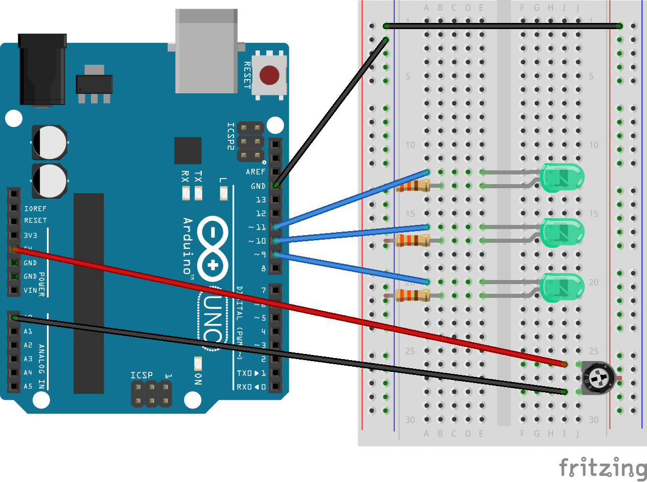
As there is only 3 LEDs used in this tutorial, I will only need to repeat the loop 3 times, and hence the condition of the for() loop will be i < 3. Now you may ask, how do I actually tell the Arduino which LED to turn on and which to turn off? Well, we will use a array to store the LED pins, which will be called “ledPin[]”. We will be using the digital pins 9 ,10 , 11 for this tutorial, and this values will be stored in ledPin[].
The potentiometer will be used to determine the delay of each LED, which turning anti-clockwise will make the delay shorter. The values of the potentiometer will be mapped from a range of 0 – 1023 to a range of 10 – 500, as this will determine the delay between each LED.
Components
- Arduino Uno Board x 1
- Green LEDs x 3
- 330Ω Resistors x 3
- Jumper Wires x 7
- Potentiometer x 1
- Breadboard
Demo
Code
The code below is different from the one you see in the video, with the code being reorganized and shorter.
/*
 *  Cyan Infinite
 *  > https://cyaninfinite.com
 *
 * ====================================
 *  Simple LED Light Chaser (3 LEDs)
 * ====================================
 * A simple (3) LED lightchaser that turn on sequentially & repeats.
 *
 */

int potPin = 0; // Input pin for the potentiometer
int delayLED = 100; // default delay for led's (microseconds)
int pValue = 0;		//To store raw value of potentiometer
int ledPin[] = {9, 10, 11};

void setup() {
for(int i = 0; i<3;i++){
pinMode(ledPin[i], OUTPUT);
}

Serial.begin(9600); //Monitor value of potentiometer
}

void loop() {
  pValue = analogRead(potPin);             // Read the value from potentiometer
  pValue = map(pValue, 0, 1023, 10, 500);  // Map pValue from 0-1023 to 10-500
  delayLED = pValue;                       // pValue is used to pause between LEDs (in milliseconds)
  Serial.println(pValue); 	           //Print delay in Serial Monitor

 for(int i = 0; i < 3; i++){
  digitalWrite(ledPin[i], HIGH);  //Turns LED On
  delay(delayLED);                //Delay by delayLED millisecond
  digitalWrite(ledPin[i], LOW);   //Turns LED Off
  delay(delayLED);
 }
}
Going further
Want to challenge yourself? Here are some things you can try out:
- Make a 12 LED light chaser
- Make a fading LED light chaser (or “LED rain” light chaser)
- Make a RGB LED light chaser
Reference
- More on potentiometer: http://www.arduino.cc/en/tutorial/potentiometer
- More on for() loop: http://www.cprogramming.com/tutorial/c/lesson3.html
- Online Syntax Highlighter: http://hilite.me
- Fritzing: http://fritzing.org/home/
LED light chaser using 74HC595 Shift Register & Potentiometer
Published: 29 March 2014, Updated: 04 September 2019
This Arduino project is similar to the other light chaser project I done, but I’ll be using a shift register to control 8 LEDs instead.
Overview
In this project, a shift register is used to handle the 8 LEDs attached to the breadboard, turning on all the LEDs one after another and turning off all of it after all the LEDs are turned on. The potentiometer is used to set the time delay between each LEDs, where I constrained the range from 0 – 1023 to 10 – 500.
Shift Register
The shift register uses a 3 pin SPI (Serial Peripheral Interface) to communicate with the Arduino, in which the the Arduino will “clock” data into the shift register through the shiftWrite() function (where the data would be push into the register). The data would be “moved” to the left when a new bit enters the register.
More information on shift register here!
Demo
Parts required
- Arduino Uno x 1
- Potentiometer x 1
- 74HC595 Shift Register IC x 1
- LED x 8
- Jumper Wires
- 330Ω Resistors x 8
Code
/*
 *  Cyan Infinite
 *  > https://cyaninfinite.com
 *
 * =======================================================
 *  LED Light Chaser (8 LEDs) with 74HC585 Shift Register
 * =======================================================
 * A shift register controlled (8) LED lightchaser that turns on then off sequentially & repeats.
 *
 */

// Pin definitions:
// The 74HC595 uses a type of serial connection called SPI
// (Serial Peripheral Interface) that requires three pins:

int potentPin = 0; // select the input pin for the potentiometer
int datapin = 2;
int clockpin = 3;
int latchpin = 4;

// We'll also declare a global variable for the data we're
// sending to the shift register:

byte data = 0;

void setup()
{
  // Set the three SPI pins to be outputs:
  pinMode(datapin, OUTPUT);
  pinMode(clockpin, OUTPUT);
  pinMode(latchpin, OUTPUT);
  Serial.begin(9600);			// Begin serial with Baudrate of 9600
}


void loop()
{
  int index;
  int pValue;               // Value of potentiometer
  int delayTime;            // Time (milliseconds) to pause between LEDs
  // Turn all the LEDs on:
  for(index = 0; index <= 7; index++)
  {
    shiftWrite(index, HIGH);
    readSensor();
  }
  // Turn all the LEDs off:
  for(index = 7; index >= 0; index--)
  {
    shiftWrite(index, LOW);
    readSensor();
  }
}

void readSensor(){
  int pValue = analogRead(potentPin);		// read the value from the sensor:
  int delayTime = 0;            			// Time (milliseconds) to pause between LEDs
  pValue = map(pValue, 0, 1023, 10, 500);	// Remap the Sensor value from 0 <-> 1023 to 10 <-> 50
  delayTime = pValue;            			// Assign it with pValue
  Serial.println(delayTime); 				// Serial print delay value
  delay(delayTime);
}


void shiftWrite(int desiredPin, boolean desiredState)
{
  bitWrite(data,desiredPin,desiredState);
  shiftOut(datapin, clockpin, MSBFIRST, data);
  digitalWrite(latchpin, HIGH);
  digitalWrite(latchpin, LOW);
}