Contents
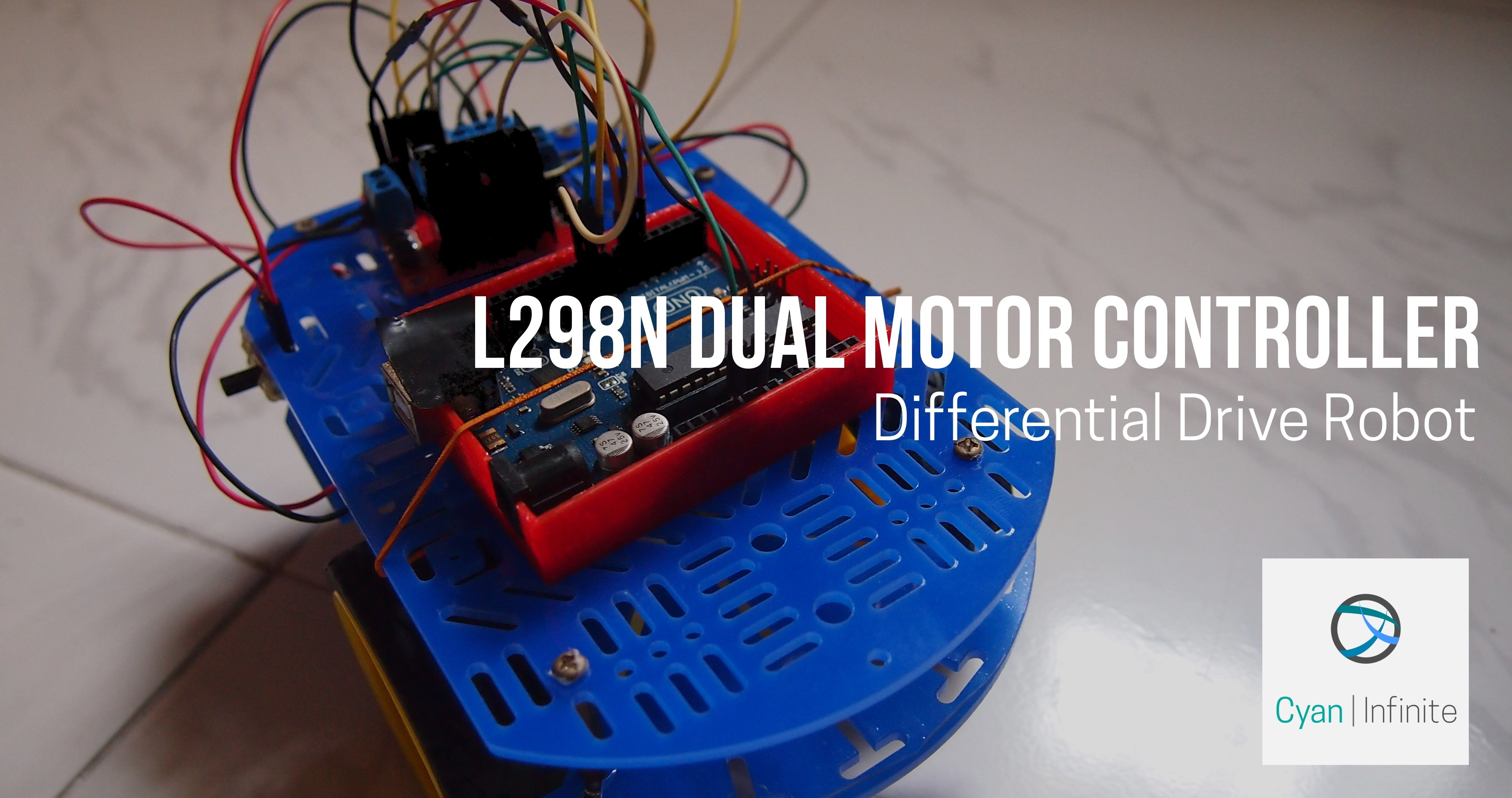
Make a simple differential robot with Arduino & the L298N Dual Motor Controller !
Brief Overview
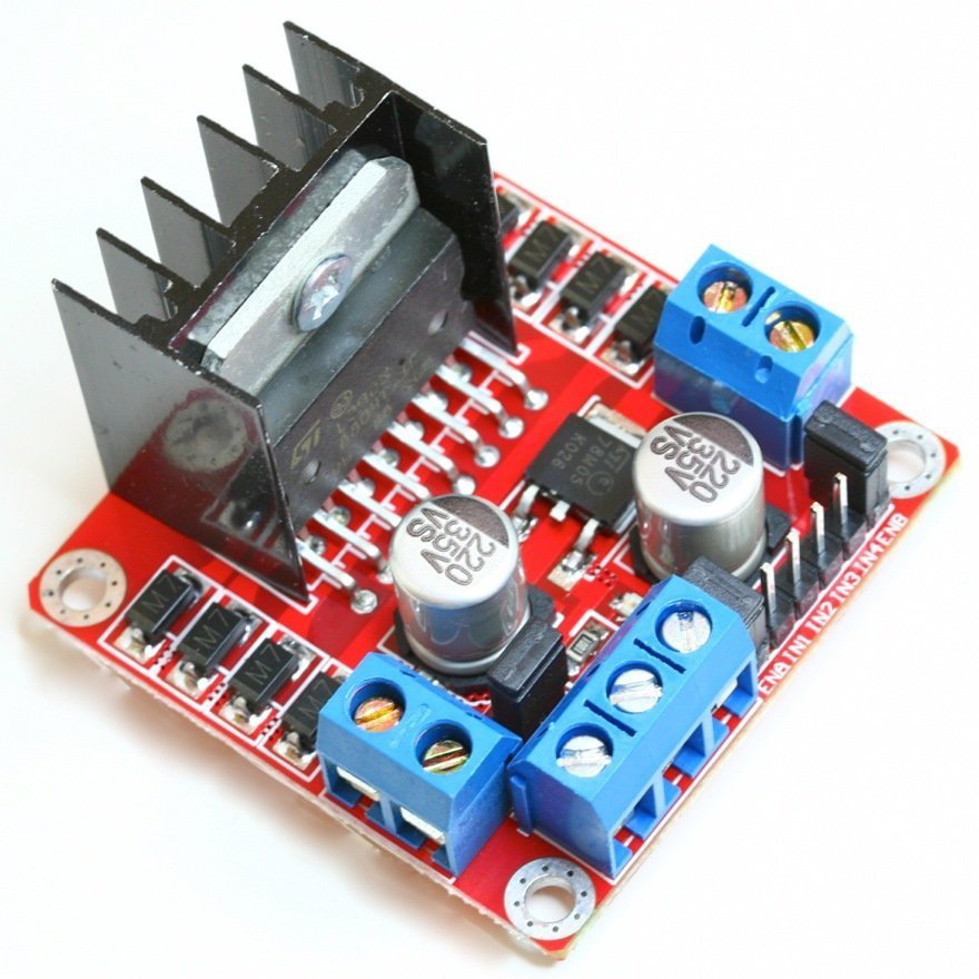
This motor controller uses the L298N H-bridge IC, which is able to control the speed and direction of two DC motors (with a voltage range of 5 – 35V DC) easily. Besides that, there is also a 5V regulator within the module, where it is able to output 5V from the module. Below are more specifications for this motor controller:
- Logical voltage: 5V
- Logical current: 0mA-36mA
- Drive current: 2A (MAX single bridge)
- Max power: 25W
- Weight: 30g
- Size: 43 x 43 x 27mm
Interfacing
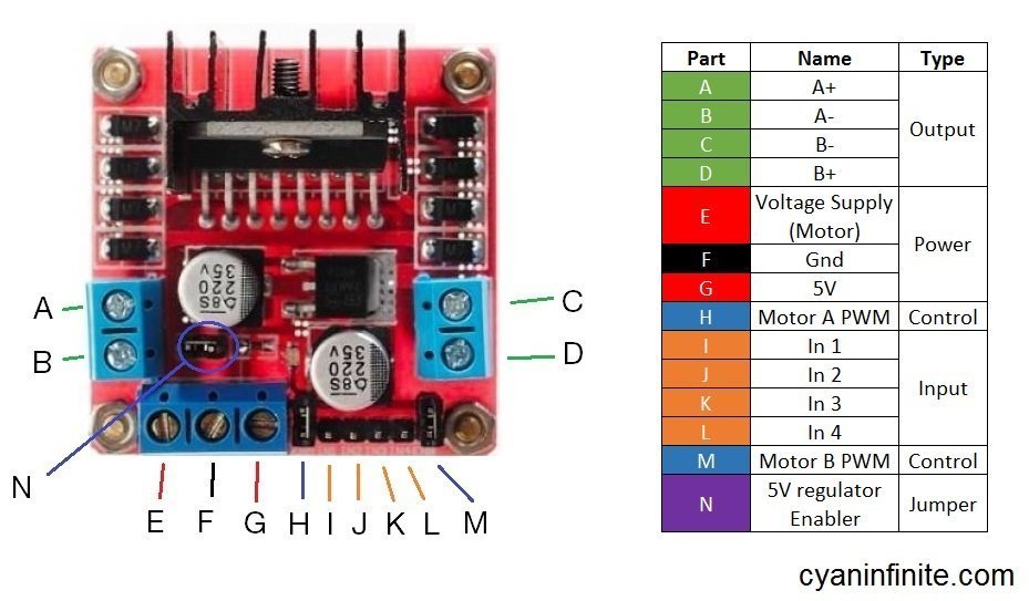
Let’s take a look at the Motor Controller layout before we proceed on to how this controller works. The table below explains the function of the parts more in depth:
Part(s):
| A – D | Outputs voltage to motors A (Left) & B (Right) respectively. |
| E | Voltage supply for the motor. One can supply 5 -to 35V DC into here, but if you are supplying higher than 12V, please remove the jumper at Part N. |
| F | Ground. Make sure that the ground of the micro-controller is connected here too (if it is used to control the controller) so as to have a “common ground”. |
| G | Outputs 5V if 12V jumper intact. |
| H | DC motor speed control for Motor A (Left). (Remove jumper for speed control with PWM) |
| I – L | Inputs to control motors A & B |
| M | DC motor speed control for Motor B (Right). (Remove jumper for speed control with PWM) |
| N | 12V Jumper. 5V Regulator is active when jumper is there. |
Differential Drive Robot
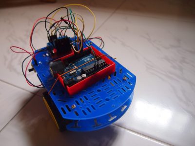
With this motor controller, we can create a differential drive robot using an Arduino and 2 motors.
Partlist
Here are the parts required to build the robot:
- Arduino Uno
- L298N Motor Controler
- Motors X 2
- 4 X AA Battery Holder
Schematics
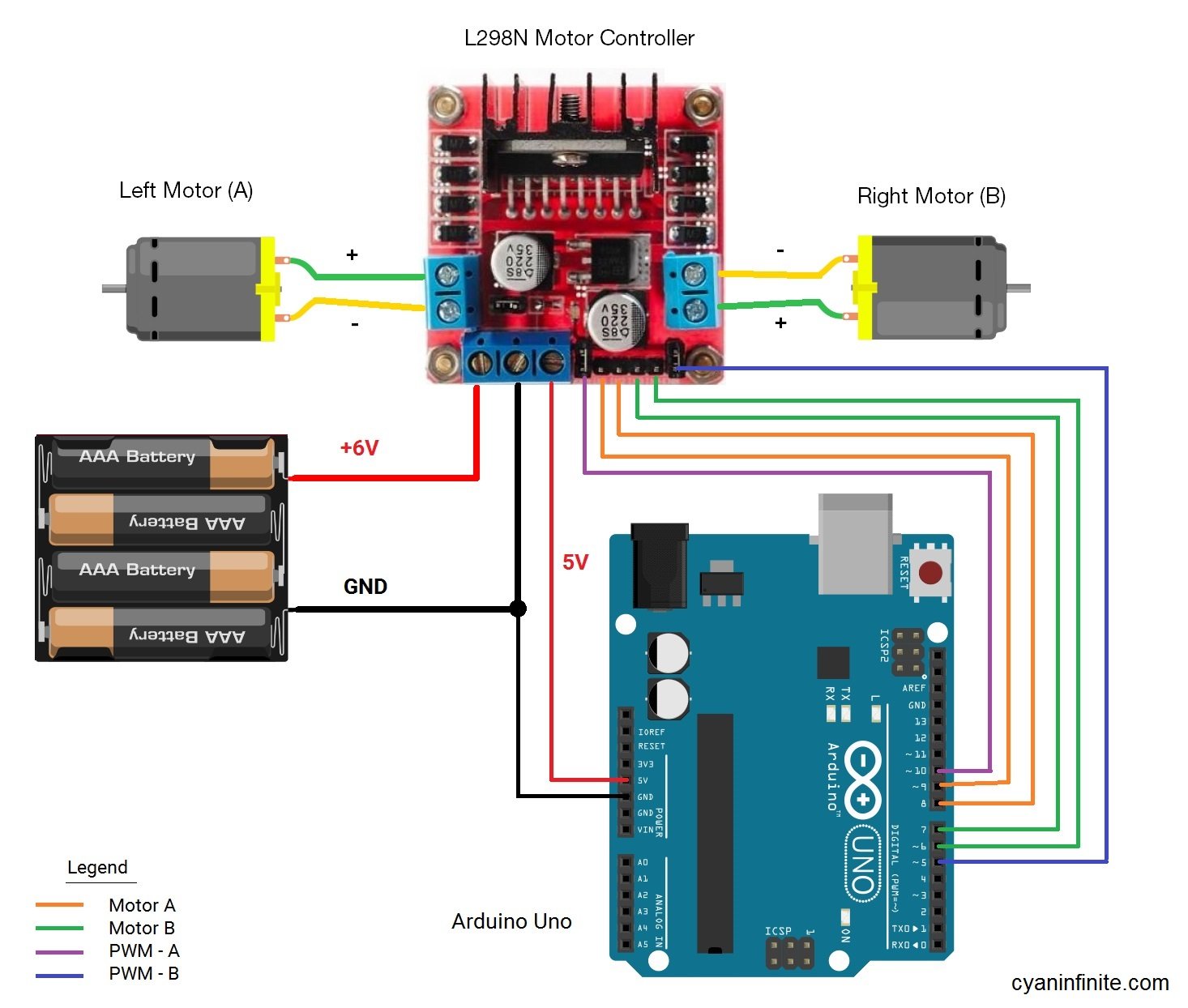
Here is the schematic of the robot. A 6V supply will be used to power both the motor controller and the arduino. (NOTE: The jumpers of the respective PWM control pin should be remove as to be able to be connected to the Arduino.
Demo
[Coming soon…]
Gallery
Code
// Left Motor (A)
int enA = 10;
int in1 = 9;
int in2 = 8;
// Right Motor (B)
int enB = 5;
int in3 = 7;
int in4 = 6;

void setup()
{
  // Declare motor control pins to be in output
  pinMode(enA, OUTPUT);
  pinMode(enB, OUTPUT);
  pinMode(in1, OUTPUT);
  pinMode(in2, OUTPUT);
  pinMode(in3, OUTPUT);
  pinMode(in4, OUTPUT);
  // A 2s delay before starting main loop
  // The LED at pin 13 will turn on for ~2s to indicate delay
  digitalWrite(13, HIGH);
  delay(1900);
  digitalWrite(13, LOW);
  delay(100);

}

/*  Move forward function
 *  Dir (Boolean) { true: Forward,
 *        false: Backward }
 *  Spd (Int) { 0 <-> 255 }
 *  Dur (Int) { Duration (in ms) }
 */

void moveBot(bool dir, int spd, int dur){
  // Motor A
  digitalWrite(in1, dir);
  digitalWrite(in2, !dir);  //The '!' symbol inverts the boolean value. So for example, if dir is true, !dir is false.
  // Motor B
  digitalWrite(in3, dir);
  digitalWrite(in4, !dir);
  // Set motor speed to spd
  analogWrite(enA, spd);
  analogWrite(enB, spd);
  //Motion Duration
  delay(dur);
}

/*  Rotate function
 *  Dir (Boolean) { true: Clockwise,
 *        false: Anti-clockwise }
 *  Spd (Int) { 0 <-> 255 }
 *  Dur (Int) { Duration (in ms) }
 */

void rotateBot(bool dir, int spd, int dur){
  // Motor A
  digitalWrite(in1, dir);
  digitalWrite(in2, !dir);  //The '!' symbol inverts the boolean value. So for example, if dir is true, !dir is false.
  // Motor B
  digitalWrite(in3, !dir);
  digitalWrite(in4, dir);
  // Set motor speed to spd
  analogWrite(enA, spd);
  analogWrite(enB, spd);
  //Rotation Duration
  delay(dur);
}

//Turn off both motors
void stopMotors(){
  digitalWrite(in1, LOW);
  digitalWrite(in2, LOW);
  digitalWrite(in3, LOW);
  digitalWrite(in4, LOW);
}

void loop()
{
  // Move forward for 2s @ speed 200
  moveBot(true, 200, 2000);
  // Rotate bot for 1s clockwise @ speed 150
  rotateBot(true, 200, 1000);
  // Move backward for 2s @ speed 200
  moveBot(false, 200, 2000);
  // Rotate bot for 1s anti-clockwise @ speed 150
  rotateBot(false, 200, 1000);
  // Stop motors for 1s @ speed 200
  stopMotors();
  delay(1000);
}
