Contents
As certain projects do not utilize all the GPIO pins on the Arduino uno board, one could look at a smaller and cheaper microcontroller chip such as the ATtiny 85 instead to suit one’s need. With that in mind, projects could be miniaturize by using the ATtiny-85 chip.
Side Note
The following posts were merged:
- Programming ATtiny 85
- Interfacing a I2C 0.96″ OLED Display with ATtiny85
- Through beam sensor with Digispark (ATtiny85 USB Development Board)
The post would be seperated into 2 main themes: firstly an introduction to the chip (including how to program the chip, etc.), followed by a few relevant projects that utilizes this particular microcontroller chip.
ATtiny85 – An overview
Published: 18 September 2014, Updated: 01 September 2019
In this tutorial, I will be showing you how to use the Arduino Uno as the programmer & arduino software to program the ATtiny85.
What is ATtiny?
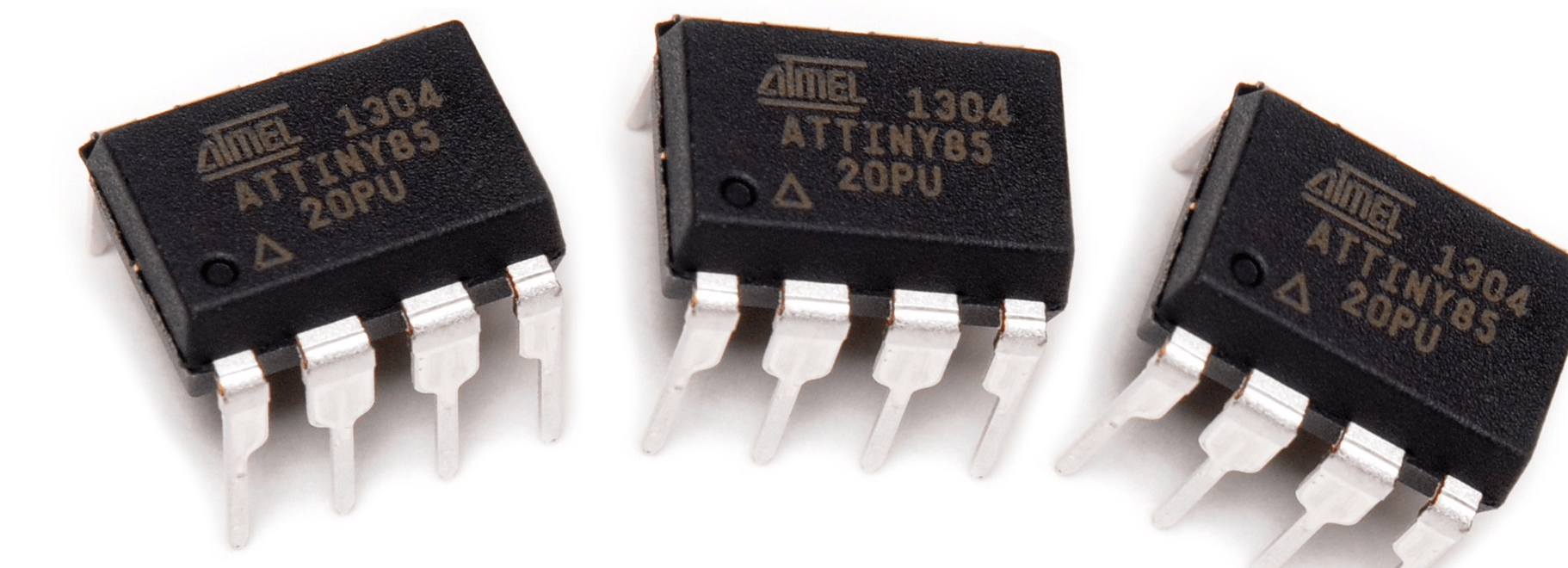
ATtiny is another series of Atmel 8-bit Microcontroller chip, which include chips such as ATtiny-45, ATtiny-84,etc. For the ATtiny85, it consists of 8 pins (5 of the pins which could be utilized for programming). As the power requirement of the chip ranges from 1.8V to 5.5V, this means that you can power the ATtiny with only a button cell / battery. Furthermore, it is re-programmable, which means that you can reprogram this chip for other projects! The ATtiny is actually very similar to the arduino board since both are from Atmel (which is bought over by Microchip), except that it has lesser GPIO (General Purpose Input/Output) pins.
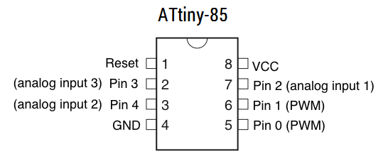
The image below shows the pin configuration of the ATtiny85:
Why use ATtiny85 instead of normal Arduino board?
ATtiny85 are:
- Smaller: Your prototype can shrink further!
- Cheaper: Can get at around 6 ATtiny85 for an Arduino Uno, I think.
- Low Power: Powering with a coin cell is possible!
- Ideal & convenient for running simpler projects (Projects that uses less GPIO pins)
Programming the ATtiny-85 chip
We would be using an Arduino Uno as an ISP (In-System Programmer) to upload the program into the ATtiny85. (Other micro controller boards or programmer could be used for more advance users.)
Components
- Arduino Uno
- ATtiny-85
- Jumper Wires
- Breadboard
- 10 uF Capacitor
- Computer with Arduino IDE 1.0
Arduino as ISP
1) Download the Arduino IDE & install it.
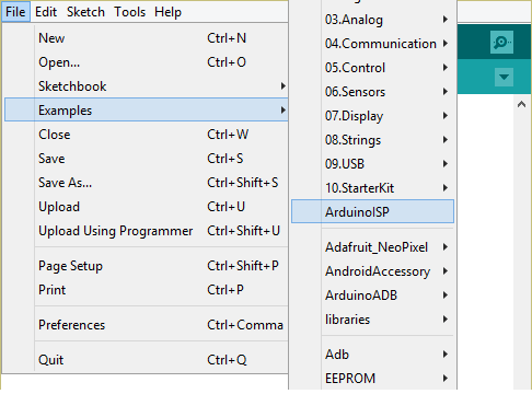
2) Open the Arduino IDE. Select File > Examples > ArduinoISP. Upload this file into the Arduino Uno. This program is to convert the Arduino Uno into an AVR ISP (In-System Programmer) for the ATtiny85, which would allow you to burn the bootloader onto the ATtiny85. (Or in other words, program the ATtiny85.)
Uploading the sketch to ATtiny85
3) Wire the Arduino Uno & the ATtiny85 using the schematics shown below. Attach a 10uF electrolytic capacitor between the RESET & GND pin, ensuring that the negative part of the capacitor is in the reset pin. (DO NOT REVERSE THE POLARITY!!! PLEASE DOUBLE CHECK THIS BEFORE PLUGGING THE USB INTO THE ARDUINO.) The capacitor is added to prevent the Arduino board from resetting (which starts the bootloader), which ensures that the Arduino IDE talks to the ArduinoISP (not the bootloader) during the upload of sketches into the ATtiny IC.
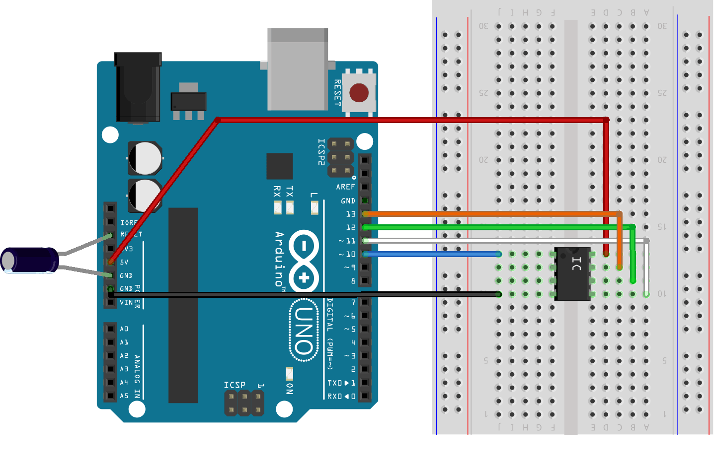
| Arduino Uno (Pins) | ATtiny-85 (Pins) |
| 5V | 8 |
| GND | 4 |
| 10 | 1 |
| 11 | 5 |
| 12 | 6 |
| 13 | 7 |
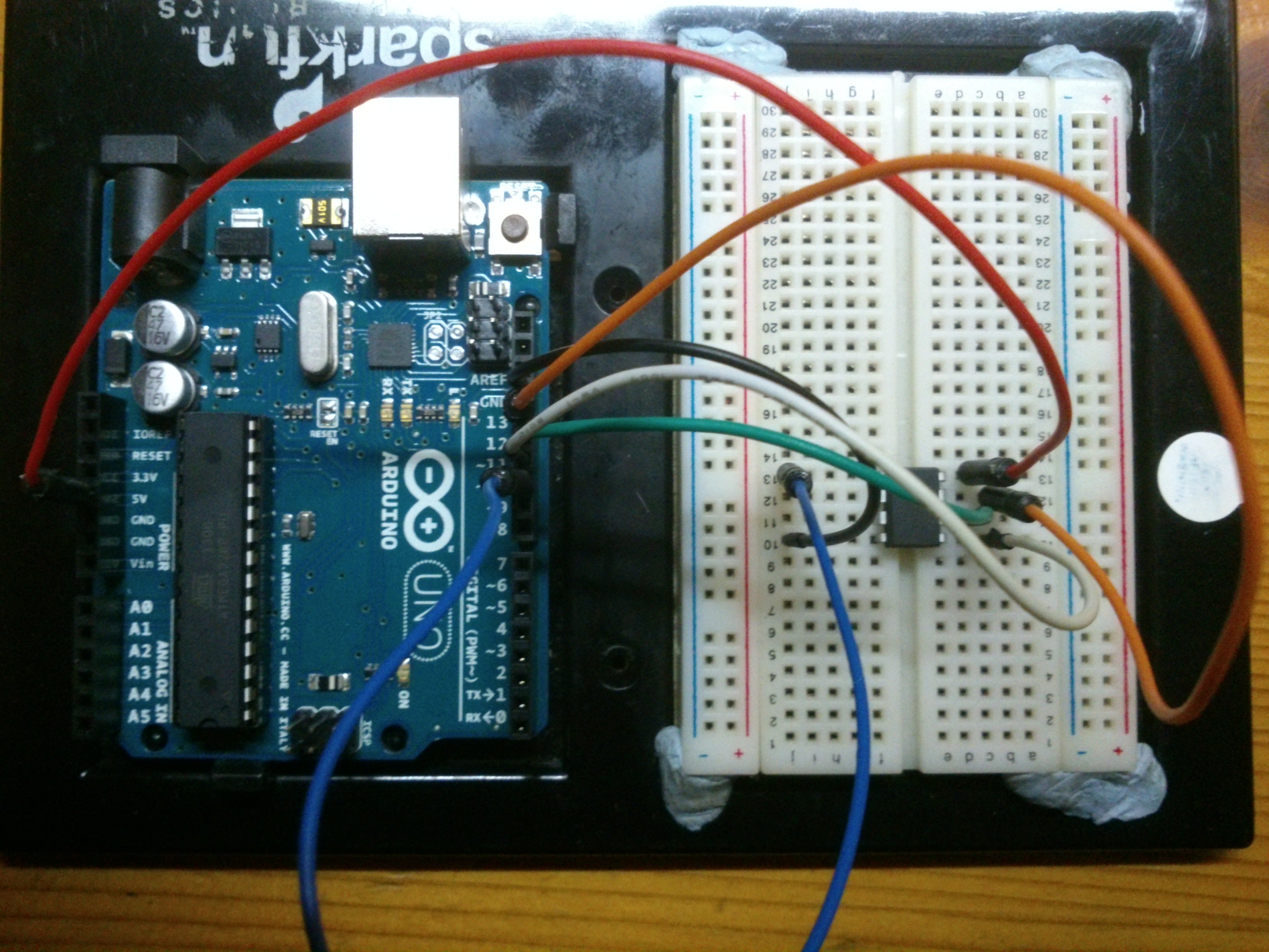
The above table shows you how the jumper wires should be connected if you don’t understand the above schematic. For example, for the first row, what the table means is to connect the Arduino Uno 5V pin to ATtiny pin 8. (Which is ATtiny Vcc pin.) Check that the connections should be similar to the set-up below:
4) Download the ATtiny files here. Extract the folders. Rename the attiny folder (not the attiny-master folder) into “hardware”.
5) Locate your arduino sketchbook location. (Which will most likely be in your documents) Copy & paste the “hardware” folder into it. Restart your Arduino IDE.
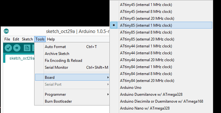
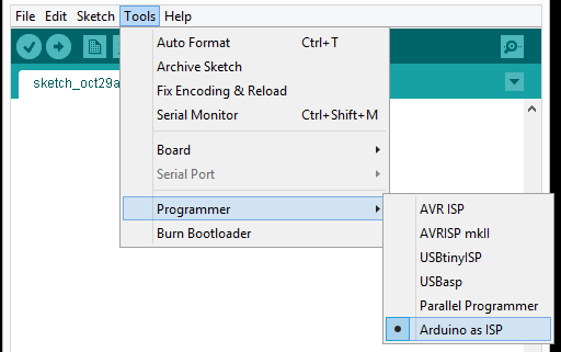
6) Go to “tools” > “boards” & select the “ATtiny 85 with 1MHz internal oscillator”. (Don’t use any of the ones that says external oscillator as you need to hookup a external crystal of the frequency.) Next,go to “tools” > “programmer” & select “Arduino as ISP”.
 |
 |
7) Let’s upload a simple program into the ATtiny to test out whether the ArduinoISP is able to program the ATtiny85.
First, go to the examples and open up the “blink” sketch. Change the line “int led = 13”; to “int led = 0”. What this means is that I’m going to output the signal to digital pin 0, which is pin 5 of the ATtiny.
Press upload. After the upload have completed, you may see 2 errors:
“avrdude: please define PAGEL and BS2 signals in the configuration file for part ATtiny85”
You should not be worried about this error, as this tells you that the ATtiny has successfully been programmed. Plug in a LED to pin 5 of the ATtiny 85 (labelled as pin 0) and connect the negative side to pin 4 (GND). It should start blinking at 1Hz.
NOTE: The ATtiny85 chip doesn’t support all the functions that the UNO does (since it’s smaller), but it supports the following:
- pinMode()
- digitalWrite()
- digitalRead()
- analogRead()
- analogWrite()
- shiftOut()
- pulseIn()
- millis()
- micros()
- delay()
- delayMicroseconds()
- SoftwareSerial
For more detailed explanation of each steps, visit highlowtech.org, since the steps are based on that website.
Moving Forward
Need inspiration on what to do with the ATtiny? Here are some interesting projects that you can draw inspiration & create with the ATtiny85:
- http://www.instructables.com/id/Dirt-cheap-ATtiny-85-Tv-B-Gone-plus-arduino-as-isp/
- http://www.instructables.com/id/ATtiny8545-POV-Display/
- http://www.instructables.com/id/Ultrasonic-Range-Finder-with-an-ATtiny85/
- http://www.instructables.com/id/IR-wireless-temperature-sensor-with-ATtiny85/
- http://www.instructables.com/id/Vibrating-Timekeeper/
Interfacing a I2C 0.96″ OLED Display with ATtiny85
Published: 20 October 2014, Updated: 03 September 2019
Time to use a tiny OLED screen with a ATtiny85 to display something! This is useful in displaying relevant information such as graphics and sensor values. In this tutorial, we’ll be going through on how a I2C 0.96″ OLED Display could be interfaced with the ATtiny85. As information on interfacing the ATtiny85 with the I2C display is scarce, this tutorial would hopefully equip one with the necessary information and knowledge on how to go about doing so.
Why use a small OLED Display?
OLED Displays do not require much power to turn it own, since no backlight is required to read the display. Furthermore, ATtiny projects do not need to have such a large screen to display all the value, and the screen of this size may be enough. Finally, with a small screen, you can make your ATtiny projects even more compact!
Which Library am I using?
For this tutorial, I’m using the Tinysaur ssd1306xled library for displaying the text on the OLED Display, as that is the only library I think is small enough to display text on the ATtiny85, although there are limitations such as there is ony 2 sizes of fonts,etc. The tinsaur library can be downloaded here.
I wanted to use the Adafruit ssd1306 library at first, for it has many graphical options such as drawing shapes and lines, but I realised that the library was too big for the ATtiny85. Therefore, I have to find a smaller library. And that is when I found the TinySaur ssd1306xled library.
Connecting the ATtiny85
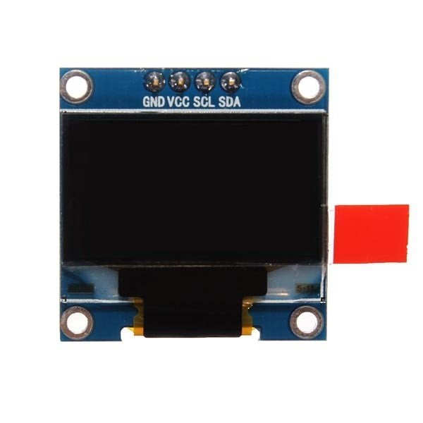
The Tinysaur library has specified the pins of where the SDA & SCL of the OLED Display should be connected to the ATtiny85. The SCL pin should be connected to ATtiny85 pin 0, and the SDA pin should be connected to ATtiny85 pin 1.
Code
I used the Tinysaur Library for this project. I changed the F_CPU constant from 1000000 to 8000000. The F_CPU constant is actually to be changed according to what speed your ATtiny is clocked. At 1000000, the flickering or the screen refresh is too obvious, so increasing the CPU clock to 8000000Hz would reduce the flickering display. To do this, you have to burn the 8MHz bootloader (to tell the chip to run at 8MHz instead of the default 1GHz).
#define F_CPU 8000000UL      //ATtiny85 CPU Clock speed (8MHz optimal[8000000], 1MHz Default[1000000])

#include <stdlib.h>
#include <avr/io.h>
#include <util/delay.h>
#include <avr/pgmspace.h>

// ----------------------------------------------------------------------------

// ---------------------	// Vcc,	Pin 1 on SSD1306 Board
// ---------------------	// GND,	Pin 2 on SSD1306 Board
#define SSD1306_SCL		PB0	// SCL,	Pin 3 on SSD1306 Board
#define SSD1306_SDA		PB1	// SDA,	Pin 4 on SSD1306 Board

#define SSD1306_SA		0x78	// Slave address

// ----------------------------------------------------------------------------

#include "ssd1306xled.h"

void setup(){
  // Small delay is necessary if ssd1306_initis the first operation in the application.
  _delay_ms(40);
  ssd1306_init();

  ssd1306_fillscreen(0x00);
  ssd1306_char_f8x16(1, 2, "Photon OS");
  ssd1306_char_f6x8(1, 5, "Loading test...");
  _delay_ms(4000);


  uint8_t p = 0xff;

  for (uint8_t i = 0; i < 4; i++)
  {
    p = (p >> i);
    ssd1306_fillscreen(~p);
    _delay_ms(1);
  }
}

void loop()
{
  ssd1306_fillscreen(0x00);
  ssd1306_char_f6x8(1, 0, "I'm a ATtiny85"); //Cannot start at 0 for x. Gives problem

  ssd1306_char_f6x8(1, 0, "I'm a small and mighty.");
  _delay_ms(5000);

  ssd1306_char_f6x8(1, 0, "Who says I can't run this LED screen?");
  _delay_ms(5000);


  ssd1306_char_f6x8(1, 0, "There am I running it now.");
  _delay_ms(5000);

}
Through beam sensor with Digispark (ATtiny85 USB Development Board)
Published: 12 September 2016, Updated: 02 September 2019
Through beam sensors can be used for a variety of applications, which include counting objects, number of steps move, etc. In this post, we will be looking at how do one interface this sensor with Digispark (ATtiny85 USB Development Board).
Brief Overview
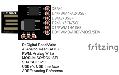
Digispark (ATtiny85 USB Board)
Digispark is a development board assembled with the ATtiny85 chip, the relevant components (such as voltage regulator, resistors, etc) and (most importantly a) USB connector, which makes programming the ATtiny85 easier. (This helps to save some effort and time compared to using a programmer to program the ATtiny85, but the only drawback is that the voltage supply is fixed by the voltage regulator onboard) For the Digispark, it comes loaded with a Digispark bootloader, allowing user to program the ATtiny85 directly by plugging the board into the USB port. Below shows the pinout of the Digispark.
Beam photoelectric infrared Sensor (LM393)
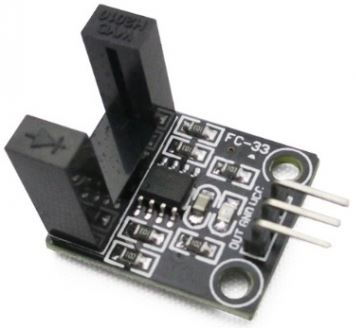
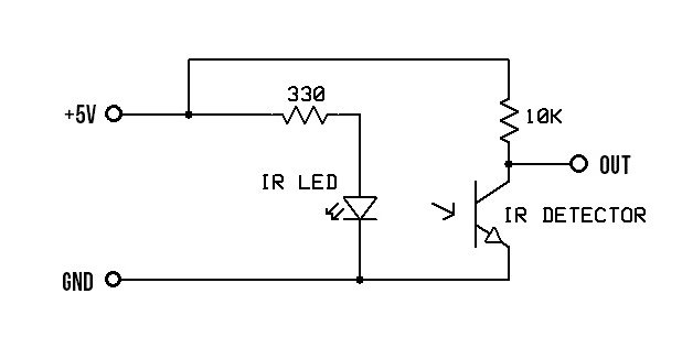
The Beam photoelectric infrared Sensor is a beam through sensor, which means that whenever an object passes through the sensor, the sensor output state will change accordingly. For this sensor, when the sensor is obstructed, it outputs a digital HIGH. Otherwise, it will output a digital LOW. The simplified workings of this sensor would look something like this, where OUT is the output pin.
Components
Below are the parts required for this tutorial:
- Digispark
- Beam photoelectric infrared Sensor
- Jumper wires
- Mini breadboard (Optional)
Setting Up
Digispark Driver
Before commencing on the main objective, we first have to setup the Digispark. As the computer would not recognise the Digispark when you plug it in, we have to install the USB driver for it. To do so, download the following package here (Select the DigisparkArduino-Win32-1.0.4-May19). Extract the contents.
Navigate to
DigisparkArduino-Win32 > DigisparkWindowsDriver
and run InstallDriver.exe to start installing the USB driver.
Arduino IDE
We’ll be using the Arduino IDE to program the Digispark. The Digispark uses Arduino IDE 1.6.5 and above, so make sure to upgrade your Arduino IDE accordingly if you need to. For the Arduino IDE, we have to download the board configuration for the Digispark. To do so, go to File > Preferences.
In the preference, insert the following link in the Additional Boards Manager URLs and click OK.
http://digistump.com/package_digistump_index.json
Next, go to Tools > Boards > Boards Manager. Search for Digi and install the Digistump AVR Boards entry.
After installation, goto Tools > Boards again, but this time we would select the Digispark (Default – 16.5mhz) option. This is to tell the Arduino IDE that the board we will be using is the Digispark board.
Hello World
We’ll be uploading the traditional “Hello World” sample into the Digispark to ensure that the board is able to communicate with the computer. To do so, we’ll be uploading a simple blink sketch into the Digispark. (File>Examples>Digispark_Example>Start)
// the setup routine runs once when you press reset:
void setup() {
  // initialize the digital pin as an output.
  pinMode(0, OUTPUT); //LED on Model B
  pinMode(1, OUTPUT); //LED on Model A
}

// the loop routine runs over and over again forever:
void loop() {
  digitalWrite(0, HIGH);   // turn the LED on (HIGH is the voltage level)
  digitalWrite(1, HIGH);
  delay(1000);               // wait for a second
  digitalWrite(0, LOW);    // turn the LED off by making the voltage LOW
  digitalWrite(1, LOW);
  delay(1000);               // wait for a second
}
Before uploading the sketch, unplug you Digispark first. Next, press the upload sketch button & wait for it to be compiled. When the console/log at the bottom of the Arduino IDE displays Plug in device now…, plug the Digispark back in.
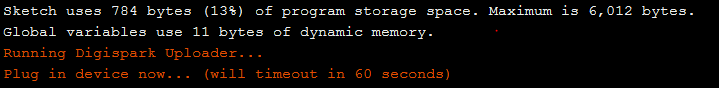
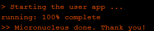
If the status shows Micronucleus done. Thank you! , it means that the program has successfully being uploaded.
With that, let’s move on to interfacing the sensor with the Digispark.
NOTE: Apparently, the Digispark can only be detected using only USB2.0, so if you plug it in a USB 3.0 port, the computer may not be able to detect the Digispark.
Interfacing
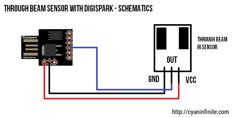
We’ll now be interfacing the sensor with the Digispark. Connect the Digispark and the sensor as shown below. We’ll be using pin P2 for reading the sensor’s output.
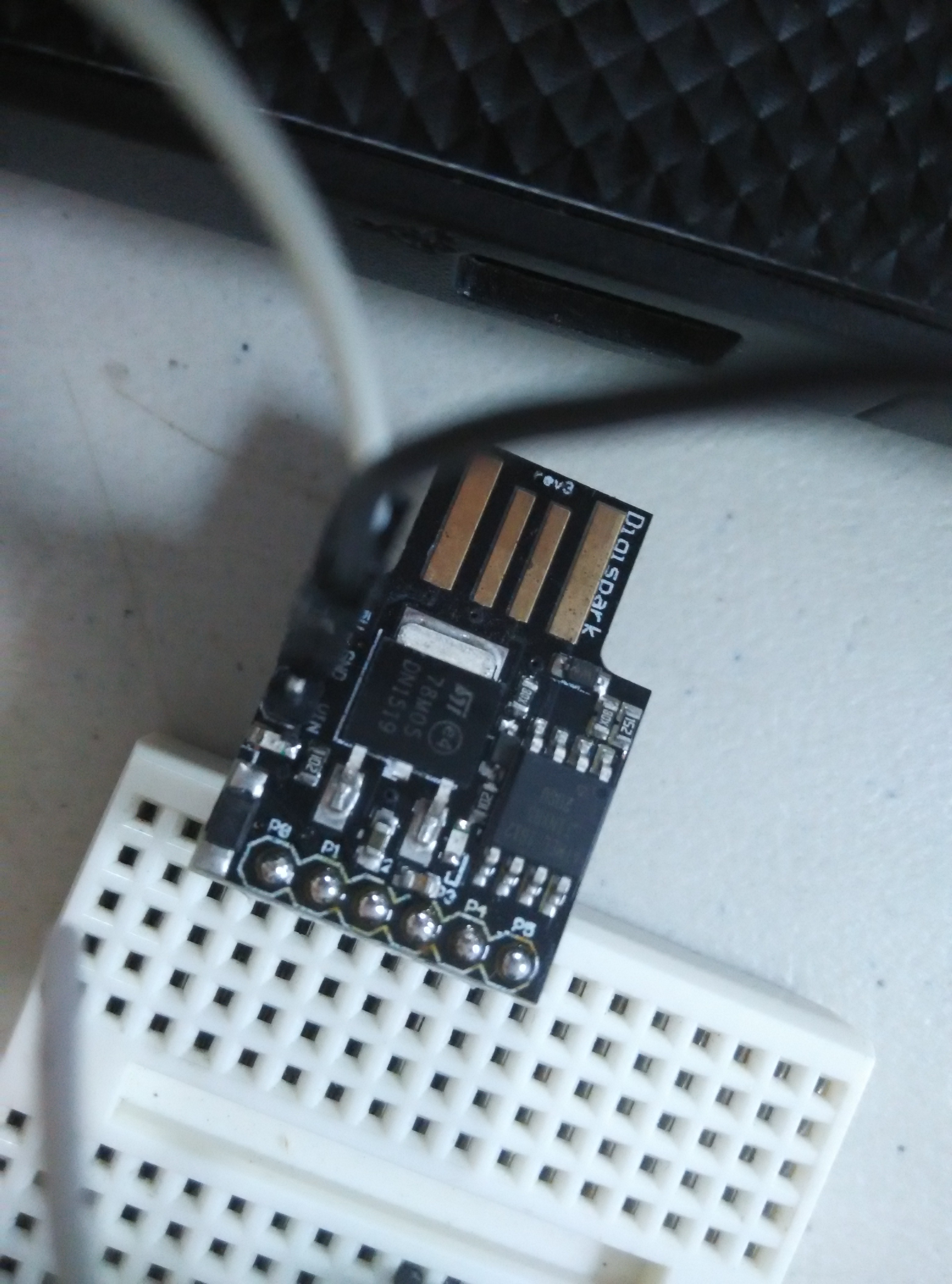
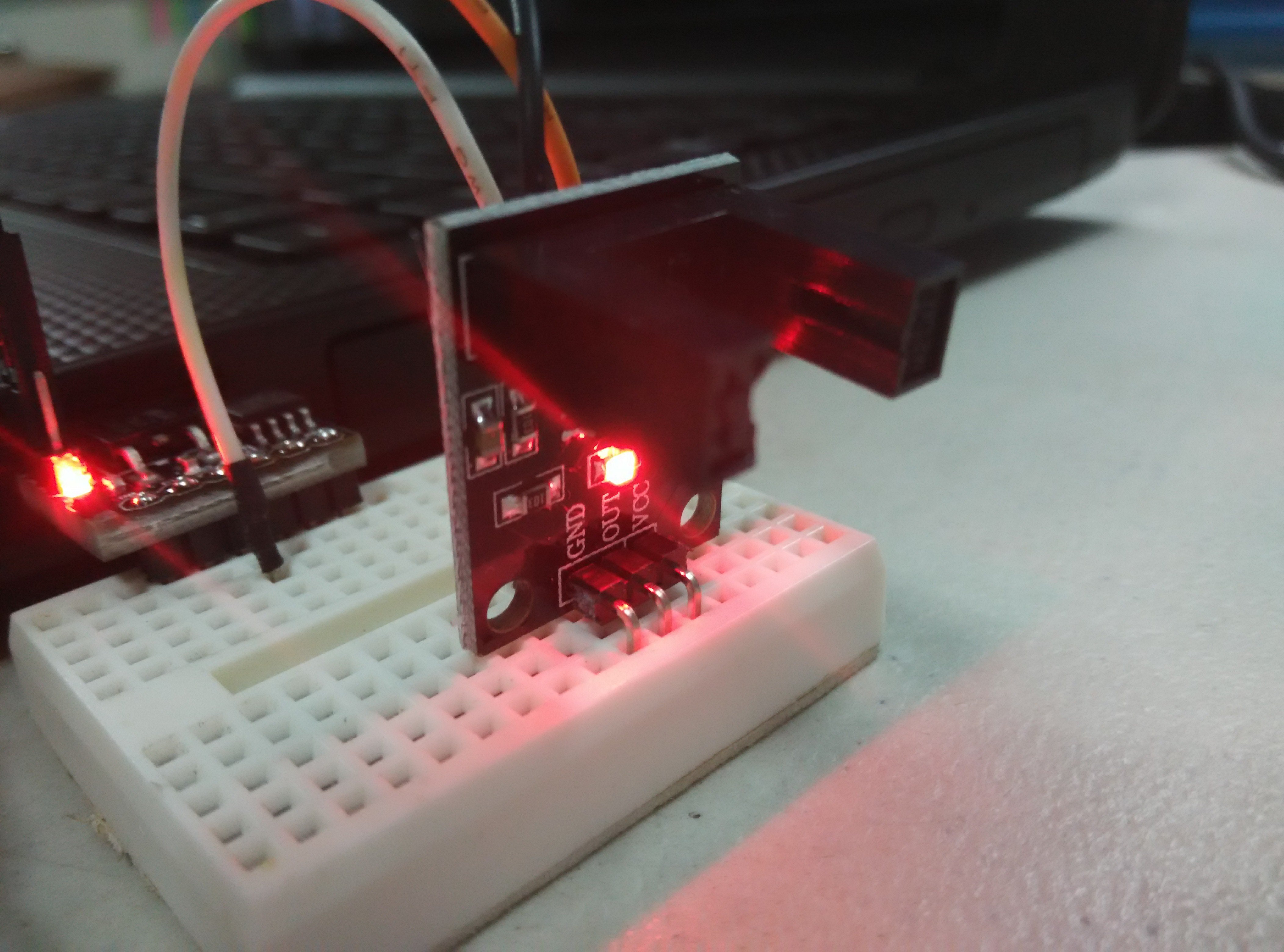
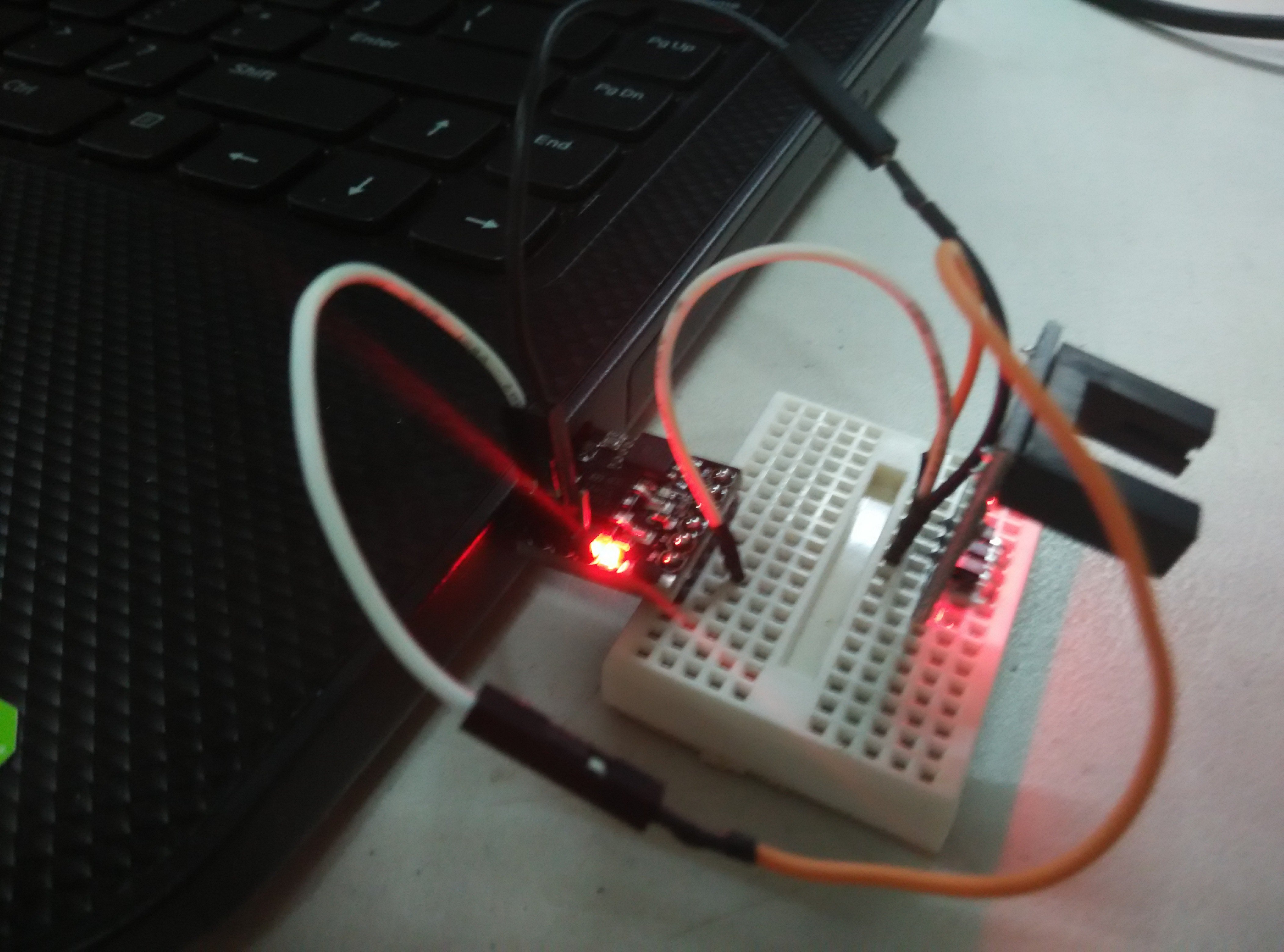
Below are a few images of how the connection should look like:
Code
Basically how the Digispark will function is that whenever the sensor is blocked, the LED on the Digispark will light up. If not, the LED will remain off.
/*
 *  Cyan Infinite
 *  > https://cyaninfinite.com
 *
 * ====================================
 *  Digispark with through beam sensor
 * ====================================
 * Turn the onboard LED on when the light beam is not detected by the sensor.
 *
 */

int state=0;  //Sensor state

void setup() {
  // initialize the digital pin as an output.
  pinMode(1, OUTPUT); //LED on the board
}

void loop() {
  state = digitalRead(2);   //Read the sensor output value
  /*
   * Write the state of the sensor output.
   * If sensor output is HIGH -> LED ON
   * If sensor output is LOW -> LED OFF
   */
  digitalWrite(1, state);
  delay(10);            // Wait for a 10ms
  }
Demo
A short demo of the code.