Contents
Looking for project ideas on ultrasonic sensor? Or curious on how these sensors would allow one to measure distance via ultrasound? Here’s a list of project realated to it for inspiration and reference!
This post conslidates all the different projects that utilises the ultrasonic sensor, and would be useful for inspiration or reference that could be included in one’s project.
Side Note
The following posts were merged:
- Ultrasonic Rangefinder
- Mini BT Ultrasonic Rangefinder
- Ultrasonic Musical Keyboard (v1 & v2)
- Arduino Ultrasonic Pong
Arduino Ultrasonic Pong
Published: 24 February 2019, Updated: 04 March 2019
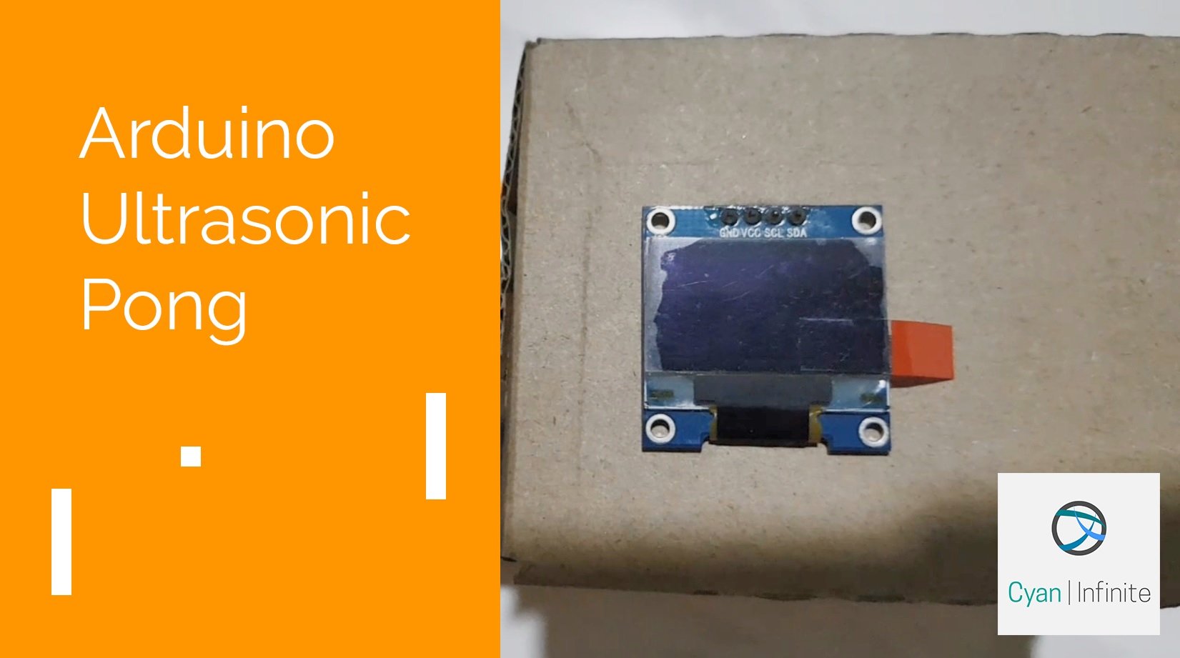
Using the prototype created as the next iteration of the ultrasonic keyboard, I decided to repurposed it into something more other than tone generation, and this is when the idea of using the ultrasonic sensor as a game interface came about.
The Classical Pong
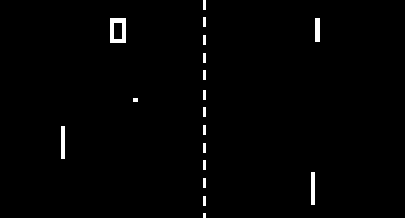
This is one of the earliest arcade game that is created in the 70s, whereby it is a simple game that simulates table tennis represented in simple 2D graphics (of rectangles & circle). The game consists of 2 rectangular paddles (which are located on the sides of the screen), with 2 players controlling one padfle each. The main objective of the game is straightforward: to reach 11 points first. Points are awarded when the other player fails to return the ball to the opposite player. (When the ball hits the left/right edge of the screen.)
Overview
Since it is a simple & graphic light, I decided to implement this game on a microcontroller (Maker Uno), using the ultrasonic sensor as a control interface to move the paddle.
Pong is typically played via keyboard, mouse, but for our project, the ultrasonic sensor is used instead.
As the game is between 2 players, there needs to be 2 controllers for each players. But, for this project, the second player would be substituted with a simple AI instead of another human player. One less hardware controller!
The scores would be reset when one of the player reaches the winningScore. (Which defaults at 11)
It would have another interesting feature: when the ultrasonic sensor does not detect a distance within the stipulated range, it would move by itself.
Hardware
| Maker Uno Board | x 1 |
| Parallax PING)) Ultrasonic Sensor (Or any other ultrasonic sensor could be used) | x 1 |
| 0.96″ OLED I2C Display | x 1 |
| Jumper Wires | x 8 |
The hardware used would be from the previous ultrasonic sensor keyboard project, consisting of the Maker Uno Board, ultrasonic sensor, and a 0.96″ OLED Display.
Software
The software of the project would be broken down into a few aspects.
“Distance-position” translation: Paddle control
The ultrasonic sensor would be used to control the left paddle, which represents the main player. (or Player One) The distance read by the ultrasonic sensor would first be remapped/translated within the game constrain, which would then be translated into the position of the paddle in the game.
Raw Ultrasonic Reading -> Map data to game constrain -> Move Paddle
The ultrasonic sensor would only move if it’s within a range from 10cm to 40cm, else the paddle would move by itself with respect to the ball’s y-axis position.
Within the range, the distance would be remapped to the constrain of the game (would be using screen height as a limit) of 0 to 64.
Graphics
We would be using the u8g2 graphics library, which would be used to draw the game interface. This would include erawing rectangles (paddle and ball) and numbers (for scoring).
The scores would be located at the center top of the screen, and the paddles would have a fixed x-axis that is 2/5 screen width away from the screen center.
uint8_t areaw = WD * 4 / 5; //Take up 4/5 of screen
...
uint8_t p1x = (WD / 2) - areaw / 2; //Paddle 1 x loc, fixed
Game Physics
The game elements needs to know how to interact with one another: such as when the ball meets the paddle, hits the sides of the screen, etc. This is when a physics engine comes in (collision detection) , followed by the game control (ball motion, paddle control).
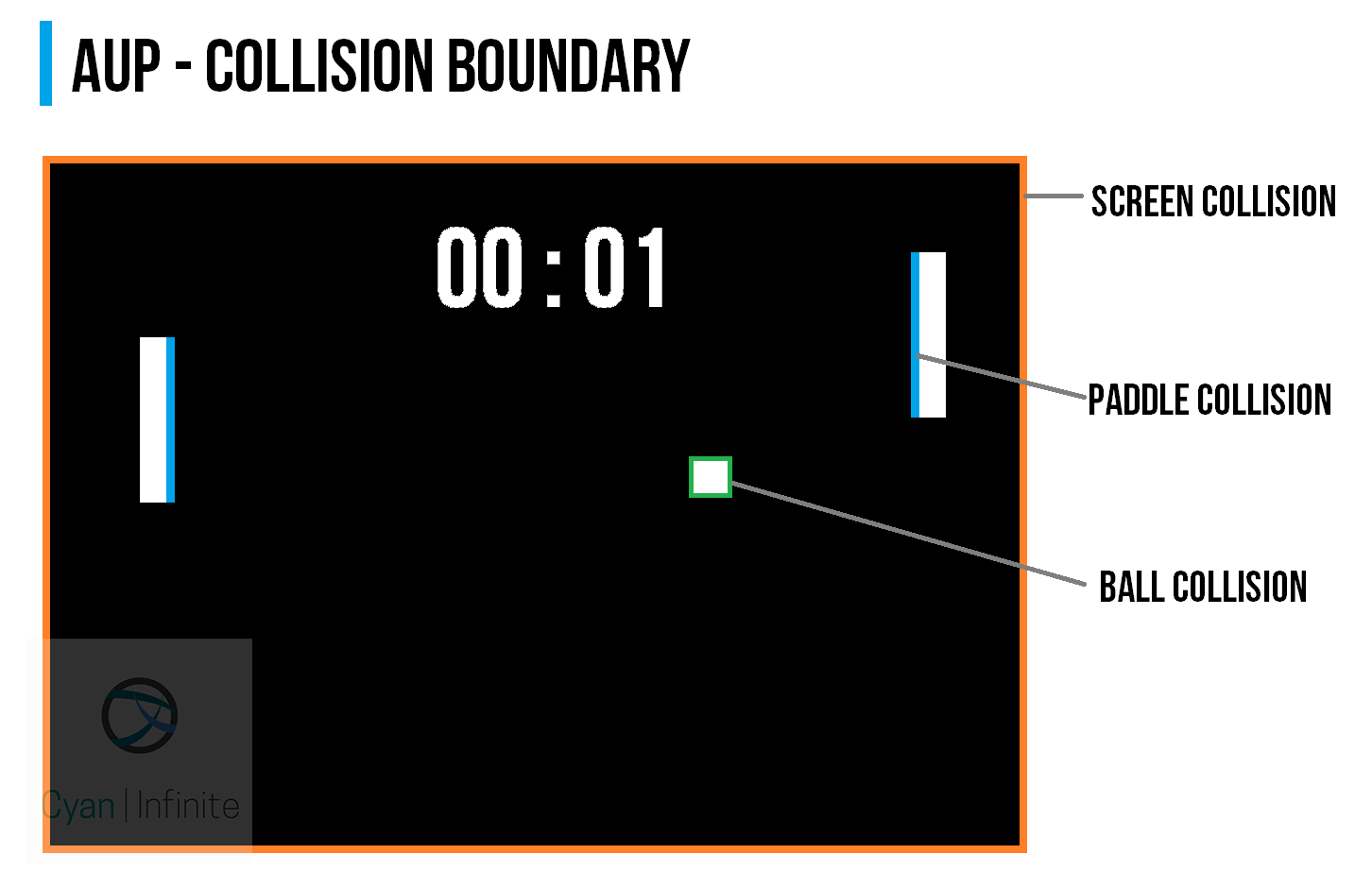
The collision engine would dictate the behaviour and response of the various game elements, such as the paddles and the ball. It comprises of a 2 parts:
- Paddle collision
- Ball collision
The paddle collision detection would limit the paddle movement within the limits stipulated (the screen), and ensures that the paddles would remain within the screen.
The ball collision detection would be implemented to respond to the following scenarios:
- Paddle contact detection
- Screen contact detection
For paddle contact detection, the position of the ball (offset with it’s width/2) would be compared to the position of the paddle (offset by the width/2 of the paddle).
- If the ball “hits” the front of the paddle, the (x-axis) direction of the ball would be reflected and would continue moving in another direction.
- If the sides of the paddle (top/bottom) are hit, the ball y-axis direction would be flipped.
Likewise for the screen detection, the ball position (with offset) would be compared to the screen position (with offset).
- If the ball hits the top/bottom of the screen, the ball (y-axis) direction would be flipped.
- If it hits the left/right sides of the screen, the player would earn a point accordingly and the game would be reset for a new round.
Scoring system
When the ball hits the left or right side of the screen, the player would did not managed to prevent the ball from hiting the screen would not score a point, whereas the opposite player would earn a point. After score addition, the game would reset to start a new round.
Ball spawning
At the start of the game (or when the game is reset), the ball would start at the center of the screen and is assigned a random speed.
Player Two
Player 2 would be controlled by simple AI, which moves according to the (y-axis) position of the ball. (Is it even considered an AI? In some way yes, I think.) The sensitivity of the paddle movement would be determined by the paddle speed variable, p2sy. (Default value: 2)
Game control/mode
There would be 2 modes: Idle mode & Active mode.
Idle mode: The paddle (Player 1) would play automatically if the ultrasonic sensor readings does not fall between the activation range specified.
//Active range,cm
uint8_t distMin = 10;
uint8_t distMax = 40;
Active mode: The sensors reading falls between the specified constrain. The position of the paddle would be determined by the distance read by the ultrasonic sensor.
Demo
Issues
There are a few issues with the program, mainly the collision detection algorithm.
- Ball gets stuck in the paddle
- Ball bounces of the left/right side of the ball
- At certain angle, the ball fails to detect the paddle and goes straight through it (which is rather frustrating to the player)
Another issue would be the ultrasonic sensor: one may experience that the paddle would move on it’s own as the player would accidentally exit the “control” range.
Conclusion
While the main goal of the project is about interfacing the ultrasonic sensor, it was the game implementation that would take up most of the time for the project. (The hardware section is really straightforward)
Through this project, one would have also learnt how to implement a simple game: collision detection of the game elements, ball and paddle behaviour, etc.
Improvement could be implemented in the future such as an improved collision detection system, including a time idle delay for the activation of automatic control of Player 1’s paddle, and many more.
Till then, have fun and enjoy the game!
Code
Version 1.0
The code is available at Github: https://github.com/1487quantum/ard-ultrasonic-pong/tree/old
/*
  Arduino Ultrasonic Pong
  >> The classic pong game that uses an ultrasonic sensor to move the paddle.
     Powered by Arduino & u8g2 lib.
  By: 1487Quantum (https://github.com/1487quantum)
*/
#include

#ifdef U8X8_HAVE_HW_I2C
#include
#endif

//Pins
#define USPIN 9         //Ultrasound

//Display
#define WD 128
#define HG 64

U8G2_SSD1306_128X64_NONAME_F_HW_I2C u8g2(U8G2_R0, /* reset=*/ U8X8_PIN_NONE);

//Ultrasound
long duration, dist;
//Active range,cm
uint8_t distMin = 10;
uint8_t distMax = 40;

//Ball
uint8_t bw = 4;   //Width & height same

//Ball coordinate
uint8_t bx = WD / 2;
uint8_t by = HG / 2;

//Ball Speed
uint8_t bsx = 3;
uint8_t bsy = 3;

//Arena: Define paddle loc
uint8_t areaw = WD * 4 / 5; //Take up 4/5 of screen

//Paddle global
//Size
uint8_t pw = bw;  //Paddle width = ball width
uint8_t ph = 5 * bw;  //Paddle 5x bigger than ball

//Paddle 1
//Loc
uint8_t p1x = (WD / 2) - areaw / 2; //Paddle 1 x loc, fixed
uint8_t p1y = 10;                   //Paddle 1 y loc,centre
//Spd
uint8_t p1sy = 3;                   //Move up/down

//Paddle 2
//Loc
uint8_t p2x = (WD / 2) + areaw / 2; //Paddle 2 x loc, fixed
uint8_t p2y = 10;                   //Paddle 2 y loc,centre
//Spd
uint8_t p2sy = 2;                   //Move up/down

//Scoring
uint8_t p1Score = 0;          //Player 1 Score
uint8_t p2Score = 0;          //Player 1 Score
uint8_t winningScore = 11;    //Score to reach to win, keep it max at 99 (else text offset needs to be changed)

//Activation range for controls
bool activeRange() {
  return  dist >= distMin && dist <= distMax ;
}

void movPaddle() {
  //Control paddle 1 via distance
  if (activeRange()) {
    p1y = map(dist, distMin, distMax, 0, HG);   //Remap distance to screen height (max)
  } else {
    if (by < p1y) {
      p1y -= p1sy;
    } else {
      p1y += p1sy;
    }
  }


  if (by < p2y) { p2y -= p2sy; } else { p2y += p2sy; } //Paddle collision if (p1y + ph > HG) {
    p1y = HG - ph;
  } else if (p1y < 0) { p1y = 0; } if (p2y + ph > HG) {
    p2y = HG - ph;
  } else if (p1y < 0) { p2y = 0; } } //Collision //Width Limit:Check whether ball is touching paddle x aixs bool withinX(uint8_t xpos) { return bx + bw >= xpos && bx <= xpos + pw; } //Height Limit:Check whether ball is touching paddle y aixs bool withinY(uint8_t ypos) { return by + bw >= ypos && by <= ypos + ph;
}

//Check for paddle front collision, isFirst true: Check collision for first paddle (Left)
bool fCollision(bool isFirst) {
  if (isFirst) {
    return bx <= p1x + pw && withinY(p1y); } else { return bx + bw >= p2x && withinY(p2y);
  }
}

//Check for paddle top/down collision, isFirst true: Check collision for first paddle (Left), if top true: check top
bool tpCollision(bool isFirst, bool top) {
  if (isFirst) {
    return top ? (by + bw >= p1y) : (by <= p1y + ph) && withinX(p1x); } else { return top ? (by + bw >= p2y) : (by <= p2y + ph) && withinX(p2x);
  }
}

void rdmSpd() {
  bsx = random(1, 5);
  bsy = random(1, 5);
}

void updatePos() {
  //Left,right collision
  if (bx - bw - 2 <= 0 || bx + bw / 2 >= WD)  {
    if (bx - bw - 2 <= 0) { p2Score++; rdmSpd(); if (p2Score >= winningScore) {
        p2Score = 0;
      }
    } else {
      p1Score++;
      rdmSpd();
      if (p1Score >= winningScore) {
        p1Score = 0;
      }
    }
    bx = WD / 2;
    by = HG / 2;
  } else if (fCollision(1) || fCollision(0)) {
    bsx = -bsx;
  }
  if (by - bw / 2 <= 0 || by + bw / 2 >= HG ) {
    // Top,Bottom edge collision
    bsy = -bsy;
  }

  bx += bsx;
  by += bsy;

  movPaddle();
}

void drawBall() {
  updatePos();
  u8g2.drawBox(bx, by, bw, bw);
}

void drawPaddle() {
  u8g2.drawBox(p1x, p1y, pw, ph);
  u8g2.drawBox(p2x, p2y, pw, ph);
}

void drawText() {
  char sc1[3];  //P1
  char sc2[3];  //P2
  char dst[8];  //Dst
  sprintf (sc1, "%02d", p1Score);   //Displays 2 digits, shows 0 when score is below 10
  sprintf (sc2, "%02d", p2Score);
  sprintf (dst, "D:%dcm", dist);

  //Scores
  u8g2.setFont(u8g2_font_fub17_tr);
  u8g2.drawStr((WD * 1 / 3) - 14, (HG / 2 ) - 12, sc1);
  u8g2.drawStr((WD / 2) - 3, (HG / 2 ) - 12, ":");
  u8g2.drawStr((WD * 2 / 3) - 8, (HG / 2 ) - 12, sc2);

  u8g2.setFont(u8g2_font_6x12_t_symbols);
  u8g2.drawStr(WD / 3, HG * 5 / 6 , dst);

}

void getDist() {
  // establish variables for duration of the ping,
  // and the distance result in inches and centimeters:

  // The PING))) is triggered by a HIGH pulse of 2 or more microseconds.
  // Give a short LOW pulse beforehand to ensure a clean HIGH pulse:
  pinMode(USPIN, OUTPUT);
  digitalWrite(USPIN, LOW);
  delayMicroseconds(2);
  digitalWrite(USPIN, HIGH);
  delayMicroseconds(5);
  digitalWrite(USPIN, LOW);

  // The same pin is used to read the signal from the PING))): a HIGH
  // pulse whose duration is the time (in microseconds) from the sending
  // of the ping to the reception of its echo off of an object.
  pinMode(USPIN, INPUT);
  duration = pulseIn(USPIN, HIGH);

  // convert the time into a distance
  dist = microsecondsToCentimeters(duration);
}

long microsecondsToCentimeters(long microseconds)
{
  // The speed of sound is 340 m/s or 29 microseconds per centimeter.
  // The ping travels out and back, so to find the distance of the
  // object we take half of the distance travelled.
  return microseconds / 29 / 2;
}

void splash() {
  u8g2.setFont(u8g2_font_t0_17_tr  );
  u8g2.drawStr((WD / 2) - 17, (HG / 2 ) + 5, "PONG");
  u8g2.sendBuffer();
  delay(3000);    //Show for 2s
}

void setup() {
  // put your setup code here, to run once:
  DDRD |= 0b11111110; // set digital  1,2- 7 to output
  DDRB = 0b00111111; // set digital  8-13 to output

  //For Maker Uno: Turn off all onboard LEDS
  PORTD &= 0;
  PORTB &= 0;

  u8g2.begin();
  u8g2.setFlipMode(0);      //To flip display
  splash();                 //Show splashscreen
}

void loop() {
  u8g2.clearBuffer();
  drawText();
  drawBall();
  getDist();
  drawPaddle();
  u8g2.sendBuffer();
}
Version 1.1 Update
The updated version of the code is found here: https://github.com/1487quantum/ard-ultrasonic-pong
New features include:
- Beep on collision
- Game Over screen at the end of the game, whereby the game would reset after 5 seconds.
- Attributes/variables related to the player’s score, paddle location is transferred to a class (Player.cpp).
Ultrasonic Musical Keyboard
Version 2.0
Published: 25 August 2018, Updated: 27 December 2018
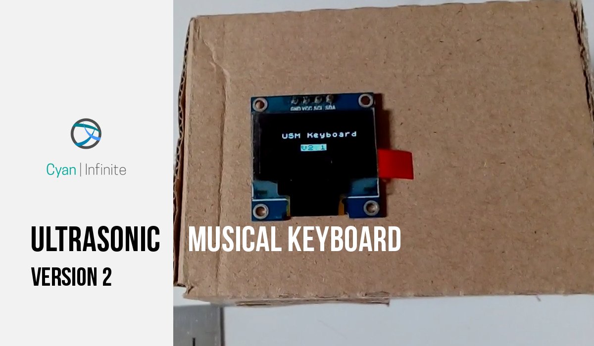
This is an updated version of the Ultrasonic Keyboard, which uses the distance of the ultrasonic sensor to play the various tones.
Overview
This is an improved version of the previous project: Ultrasonic Keyboard
It’s been sometime since I last created the Ultrasonic Keyboard, and since I have not been doing much project for some time, why not just make an improve version of the previous project? So with that, I added a 0.96″ OLED I2C Display to display the distance & the note that is currently playing. As the Maker Uno board includes a Piezo Speaker onboard, it will be used in place of an Arduino Uno with a Piezo speaker.
In order to play the various note, a range of 10cm-65cm is used, with 5cm interval that represents different notes. (A total of 13 different tones that can be played)
- 0 < dist < 10cm: No tone would be played
- 10 <= dist <= 65cm: Tones would be played accordingly
- dist > 65cm: No tones would be played
Limitations
As mentioned previously in the other post, the few limitations of using a ultrasonic sensor would include:
– Certain types of material (soft materials) would absorb the ultrasound emitted, which results in less ultrasound being reflected back & subsequently recieved by the sensor.
– As the distance of the object increases, the amount of reflected ultrasound may be reduced, which results in noisy (fluctuating) distance data recieved. (Also depends on the size/shape of the object that is being detected by the sensor.)
For more accurate distance sensing, one can consider using a time of flight sensor, which works similar to an ultrasound sensor but uses a laser beam instead of ultrasound.
Components
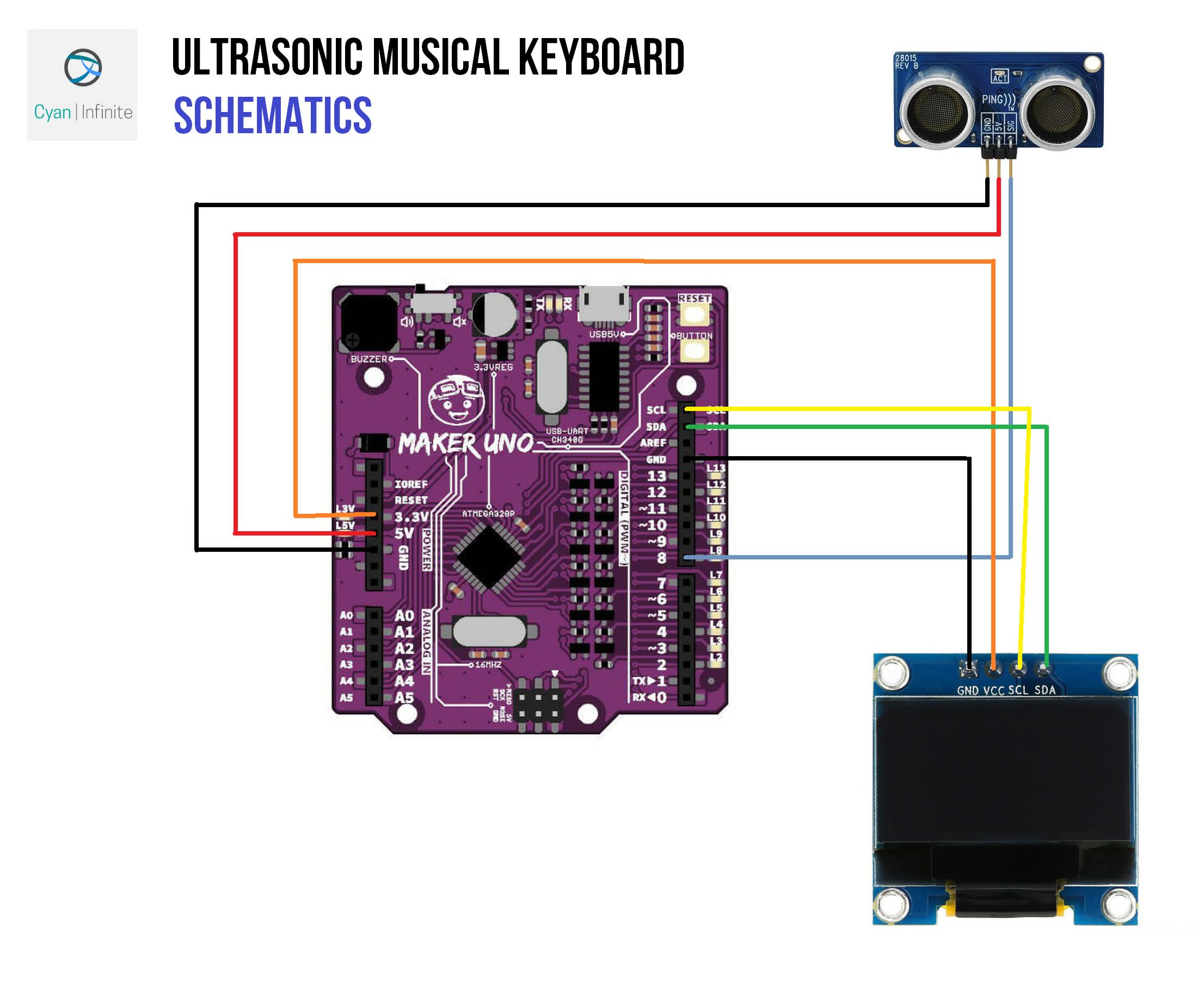
- Maker Uno x 1
- Parallax PING)) Ultrasonic Sensor x 1 [Actually any ultrasonic sensor would do, just have to change the code accordingly]
- Jumper Wires
- 0.96″ OLED Display (I2C) x 1
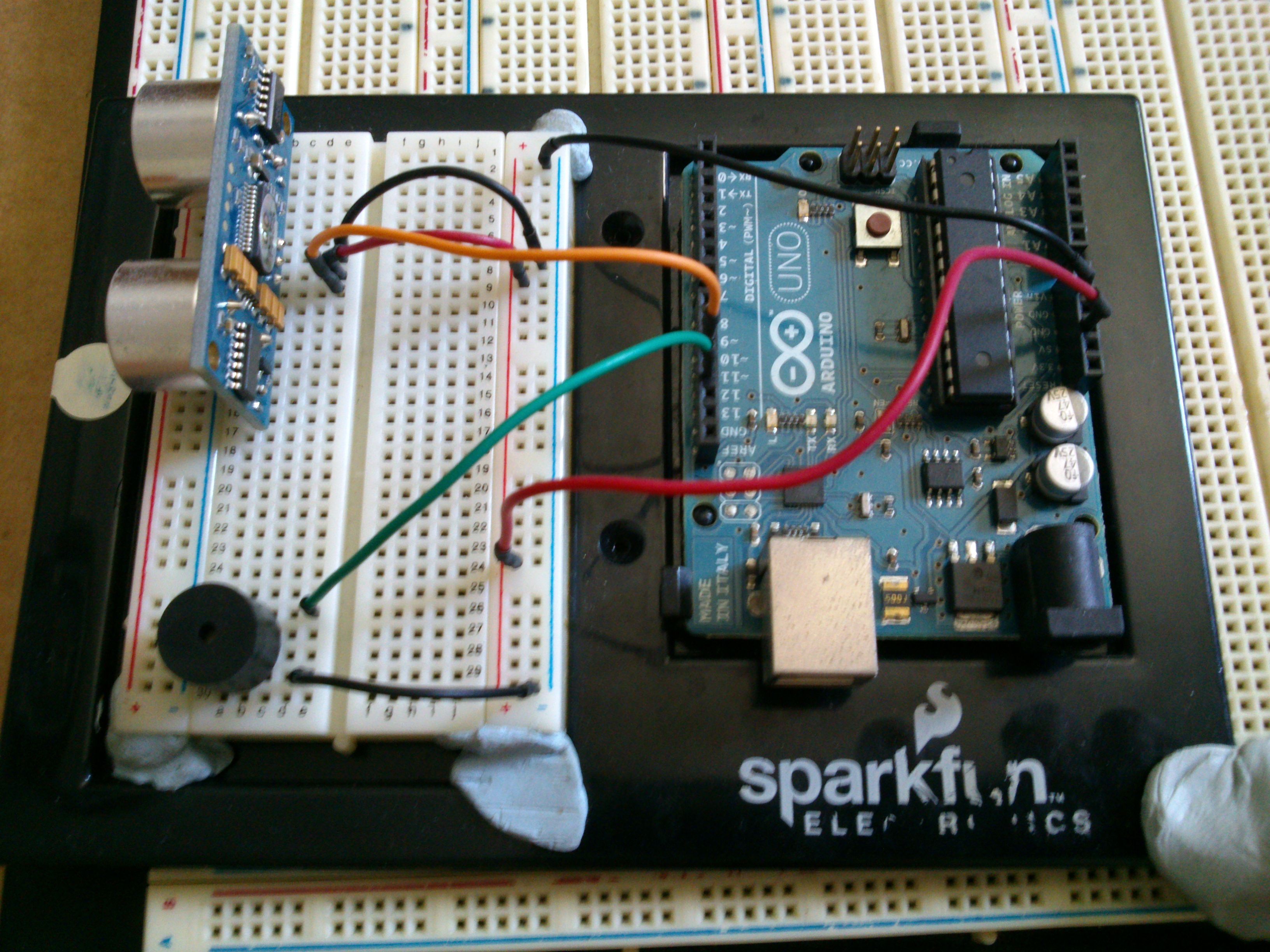
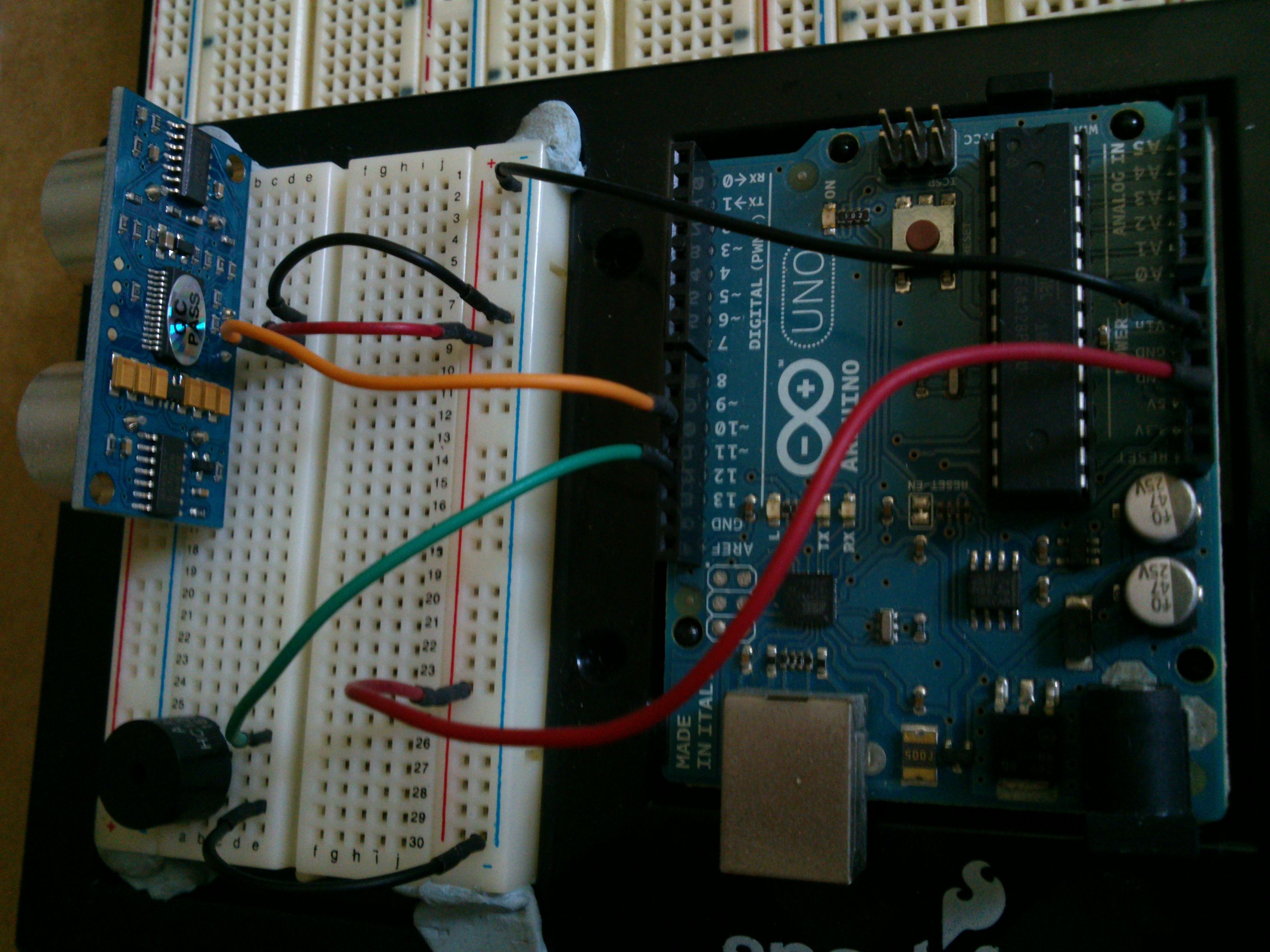
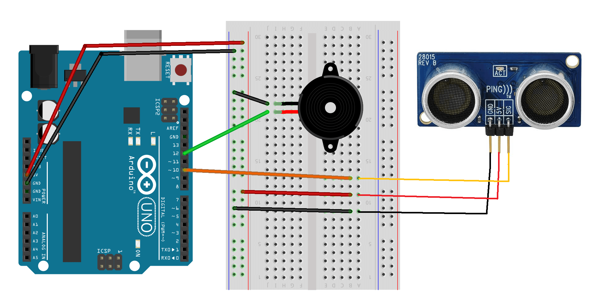
Schematics
Ensure that the buzzer toggle (on the top left corner) is set to the left, which would enable the piezo buzzer to be used.

Demo
Code
Before uploading the sketch, ensure that the u8g2 graphic library is installed as it is used to display the text.
[The code is also available on Github.]
/*
  Arduino Uno Ultrasonic Musical Keyboard
  Version 2.1

  - Uses u8g2 lib
*/
#include

//Pins
#define SPPIN 8         //Speaker
#define USPIN 9         //Ultrasound

//Display
#define WD 128
#define HG 64

//Tone
#define ITVL  5         //Interval between each note (cm)
#define T_LEN   14        //Number of notes available + 1
#define OFFSET 10 //Offset melody start distance (cm)

U8X8_SSD1306_128X64_NONAME_HW_I2C u8x8(/* reset=*/ U8X8_PIN_NONE);

bool idle = 1;          //When notes are not playing

//Tones
int notes[] = {
  262, //NOTE_C4
  277, //NOTE_CS4
  294, //NOTE_D4
  311, //NOTE_DS4
  330, //NOTE_E4
  349, //NOTE_F4
  370, //NOTE_FS4
  392, //NOTE_G4
  415, //NOTE_GS4
  440, //NOTE_A4
  466, //NOTE_AS4
  494, //NOTE_B4
  523  //NOTE_C5
};
char* names[] = { " C", " C#", " D", " D#", " E", " F", " F#", " G", " G#", " A", " A#", " B" , " C5"};

//Ultrasound
long duration, dist;

//Logo
void logo() {
  u8x8.print("1487QUANTUM");
}

//Startup screen
void splash() {
  //Display
  u8x8.setFont(u8x8_font_chroma48medium8_r);
  u8x8.setCursor(3, 2);
  u8x8.print("USM Keyboard");
  u8x8.inverse();
  u8x8.setCursor(6, 4);
  u8x8.print("V2.1");
  u8x8.noInverse();
  u8x8.setCursor(6, 6);
  for (int i = 0; i < 4; i++) { u8x8.print("."); delay(1000); } u8x8.clearDisplay(); //u8x8.setFlipMode(1); } void setup() { //Speaker->8, Ultrasound->9
  DDRD |= 0b11111110; // set digital  1,2- 7 to output
  DDRB = 0b00111111; // set digital  8-13 to output

  //For Maker Uno: Turn off all onboard LEDS
  PORTD &= 0;
  PORTB &= 0;

  u8x8.begin();
  //splash();
}

//Display
void draw(void) {
  //Font list: https://github.com/olikraus/u8g2/wiki/fntlist8x8

  //Display notes/dist
  //Draw str
  char bufN[16];   //Note
  char bufI[16];  //ID
  sprintf (bufN, "%s ", (dist > 9 && dist <= T_LEN * ITVL) ? names[(dist - OFFSET) / ITVL ] : "._."); sprintf (bufI, "DIST: %dCM", dist); u8x8.setFont(u8x8_font_saikyosansbold8_u); u8x8.draw2x2String(5, 2, bufN); u8x8.setFont(u8x8_font_victoriabold8_u ); if (idle) { u8x8.setFont(u8x8_font_pxplusibmcga_u ); u8x8.setCursor(3, 7); logo(); } else { u8x8.drawString(3, 7, bufI); } delay(100); } void loop() { // establish variables for duration of the ping, // and the distance result in inches and centimeters: // The PING))) is triggered by a HIGH pulse of 2 or more microseconds. // Give a short LOW pulse beforehand to ensure a clean HIGH pulse: pinMode(USPIN, OUTPUT); digitalWrite(USPIN, LOW); delayMicroseconds(2); digitalWrite(USPIN, HIGH); delayMicroseconds(5); digitalWrite(USPIN, LOW); // The same pin is used to read the signal from the PING))): a HIGH // pulse whose duration is the time (in microseconds) from the sending // of the ping to the reception of its echo off of an object. pinMode(USPIN, INPUT); duration = pulseIn(USPIN, HIGH); // convert the time into a distance dist = microsecondsToCentimeters(duration); if (dist > 9 && dist <= T_LEN * ITVL) {
    tone(SPPIN, notes[(dist - OFFSET) / ITVL], 500);
    idle = 0;
  } else {
    noTone(SPPIN);
    idle = 1;
  }
  draw();
}

long microsecondsToCentimeters(long microseconds)
{
  // The speed of sound is 340 m/s or 29 microseconds per centimeter.
  // The ping travels out and back, so to find the distance of the
  // object we take half of the distance traveled.
  return microseconds / 29 / 2;
}
Version 1.0
Published: 31 March 2014, Updated: 15 December 2018
It’s time to make some music using the ultrasonic sensor! This is a project that I derived from the previous tutorial, the Ultrasonic Rangefinder.
Overview
How can we make music using the ultrasonic sensor? By adding a piezo speaker, we will assign certain tones to the various range of distance detected by the ultrasonic sensor, which will be generated using the piezo speaker.
For this project, I will be constraining the distance range detected by the ultrasonic sensor from 0cm to 50cm. Hence, when the ultrasonic sensor detects distances exceeding 50cm, no tone will be produced. After constraining the distance value, I mapped the range from 0 to 12. Base on calculations, there will be a tonal change for every approximately 4.1667cm apart the respective distances.
However, there are certain problems that we will encounter. For example, the sensitivity of the ultrasonic sensor will decrease as the distance between it and a small object increases, as the small object will not be able to reflect the ultrasonic signals back to the sensor.
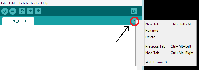
NOTE: As for the programming part, we will have to create the pitches.h file for the tones to be generated. This can be done by pressing on the “down” arrow beside the main program tab & click “New Tab”. Name the new file as pitches.h.
Parts
- Ultrasonic Sensor x 1
- Piezo speaker x 1
- Arduino Uno x 1
- Jumper wires x 1
Schematics
Demo
After testing the sensor, I attempted to play “Happy Birthday” in the following demo.
Code
// this constant won't change.  It's the pin number
// of the sensor's output:
const int pingPin = 10;

#include <SoftwareSerial.h>
#include "pitches.h"


int notes[] = {
 NOTE_C4  ,
 NOTE_CS4 ,
 NOTE_D4  ,
 NOTE_DS4 ,
 NOTE_E4  ,
 NOTE_F4  ,
 NOTE_FS4 ,
 NOTE_G4  ,
 NOTE_GS4 ,
 NOTE_A4  ,
 NOTE_AS4 ,
 NOTE_B4  ,
 NOTE_C5  ,
 };

void setup() {
  // initialize serial communication:
Serial.begin(9600);
}

void loop()
{
  // establish variables for duration of the ping,
  // and the distance result in inches and centimeters:
  long duration, inches, cm;

  // The PING))) is triggered by a HIGH pulse of 2 or more microseconds.
  // Give a short LOW pulse beforehand to ensure a clean HIGH pulse:
  pinMode(pingPin, OUTPUT);
  digitalWrite(pingPin, LOW);
  delayMicroseconds(2);
  digitalWrite(pingPin, HIGH);
  delayMicroseconds(5);
  digitalWrite(pingPin, LOW);

  // The same pin is used to read the signal from the PING))): a HIGH
  // pulse whose duration is the time (in microseconds) from the sending
  // of the ping to the reception of its echo off of an object.
  pinMode(pingPin, INPUT);
  duration = pulseIn(pingPin, HIGH);

  // convert the time into a distance
  cm = microsecondsToCentimeters(duration);

  if(cm>50){
    //turn off sound
noTone(12);
  }else{
 cm = constrain(cm, 0, 50);
  }
 cm = map(cm, 0, 50, 0, 12);
  tone(12, notes[cm], 500);

  Serial.print(cm);
  Serial.print("cm");
  Serial.println();


  delay(10);
}


long microsecondsToCentimeters(long microseconds)
{
  // The speed of sound is 340 m/s or 29 microseconds per centimeter.
  // The ping travels out and back, so to find the distance of the
  // object we take half of the distance travelled.
  return microseconds / 29 / 2;
}
Mini BT Ultrasonic Rangefinder
Published: 10 May 2015, Updated: 24 December 2018
During the weekend, I wanted to create a simple Arduino project that would not take more than 30 minutes, so I have decided to come up with this portable Bluetooth-based ultrasonic range finder. Using Bluetooth to transmit the value to the smartphone, this is useful as a mean to measure things without the need of using rulers or measuring tape.
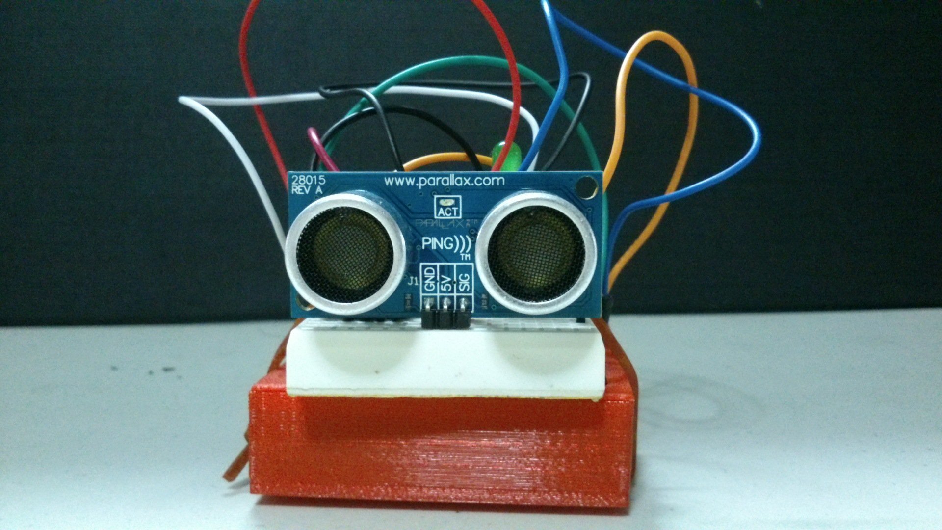
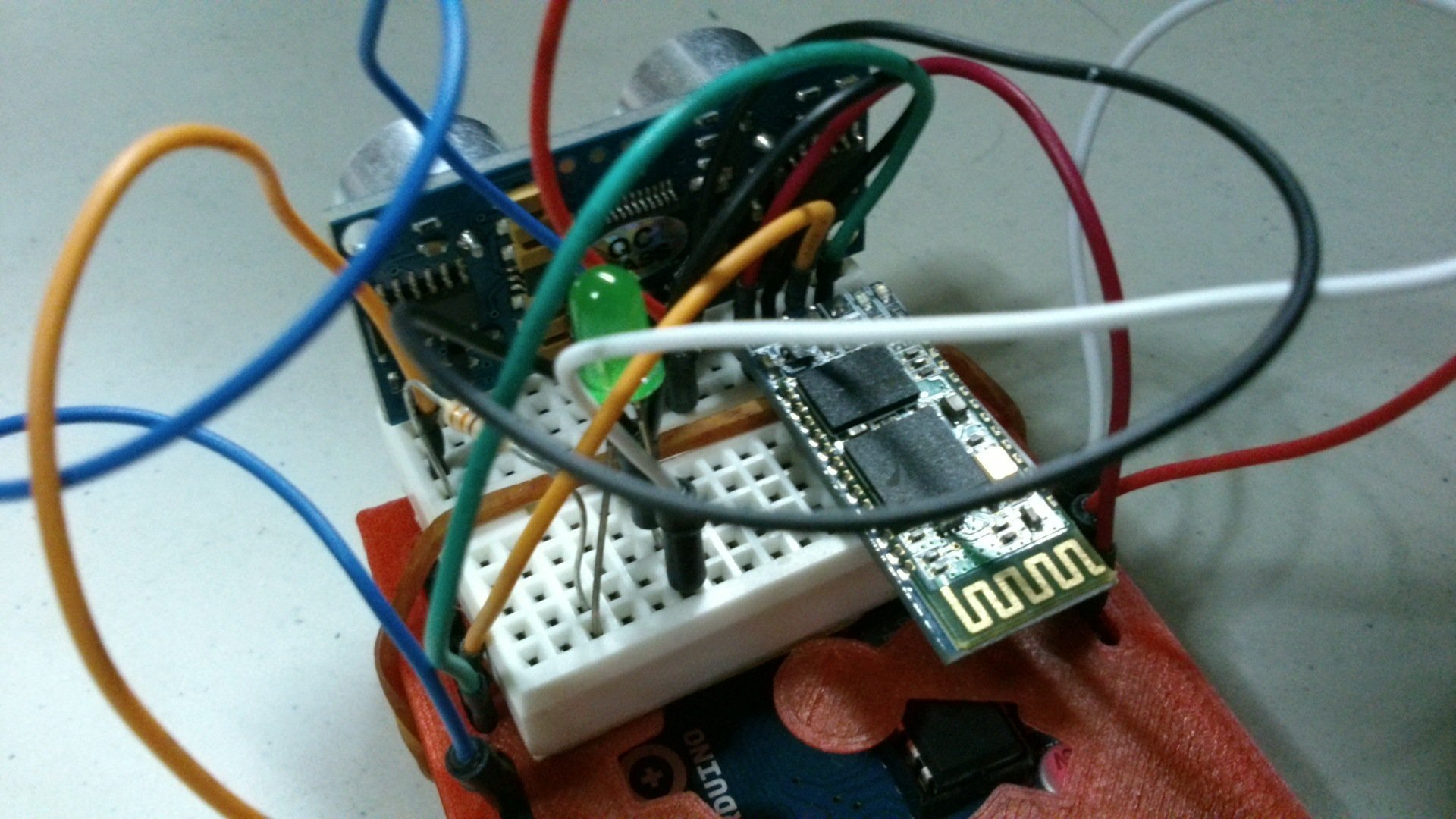
Gallery


Demo
Code
#include <SoftwareSerial.h>  // import the serial library

SoftwareSerial BTSerial(7, 6); // RX, TX

const int usPin = 9;  //Ultrasonic sensor pin

void setup() {
  // put your setup code here, to run once:
  BTSerial.begin(9600);
  BTSerial.println("Initialising...Ready");
}

void loop() {
  // establish variables for duration of the ping,
  // and the distance result in inches and centimeters:
  long duration, cm;

  // The PING))) is triggered by a HIGH pulse of 2 or more microseconds.
  // Give a short LOW pulse beforehand to ensure a clean HIGH pulse:
  pinMode(usPin, OUTPUT);
  digitalWrite(usPin, LOW);
  delayMicroseconds(2);
  digitalWrite(usPin, HIGH);
  delayMicroseconds(5);
  digitalWrite(usPin, LOW);

  // The same pin is used to read the signal from the PING))): a HIGH
  // pulse whose duration is the time (in microseconds) from the sending
  // of the ping to the reception of its echo off of an object.
  pinMode(usPin, INPUT);
  duration = pulseIn(usPin, HIGH);

  // convert the time into a distance
  cm = microsecondsToCentimeters(duration);

  BTSerial.println(cm);
  delay(100);
}

long microsecondsToCentimeters(long microseconds)
{
  // The speed of sound is 340 m/s or 29 microseconds per centimeter.
  // The ping travels out and back, so to find the distance of the
  // object we take half of the distance travelled.
  return microseconds / 29 / 2;
}
Ultrasonic Rangefinder
Published: 28 March 2014, Updated: 03 September 2019
Today, I’ll be showing you how a ultrasonic sensor can be used to determine the distance of an object from the sensor, which will be displayed on a LCD display. In this tutorial, I’ll be using a Parallax ultrasonic sensor & a parallax serial LCD Display.
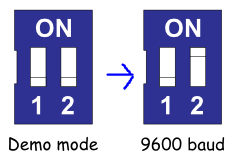
Configuration of Serial LCD
In this tutorial, I’ll be using 9600 baud rate, hence you have to switch the Serial LCD mode to 9600 baud. This can be done by switching the 2 DIP switches (on the rear of the panel) as shown below.
How will it look like?

Components
- Ultrasonic Sensor x 1
- LCD Display x 1
- Arduino Uno x 1
- Jumper wires x 1
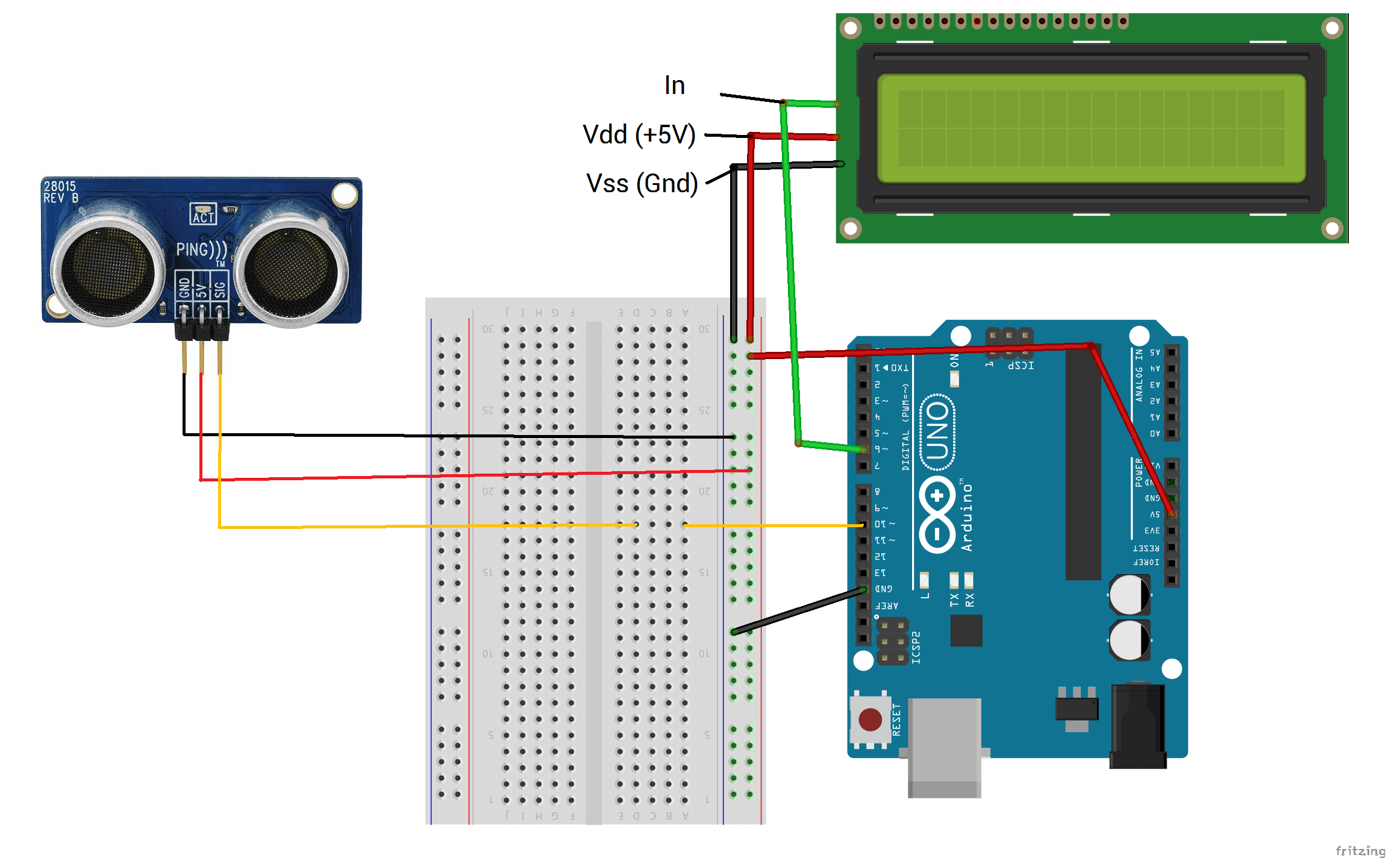
Schematics
Demo
Code
[The code was adapted from the sample PING program found in the Arduino IDE. (Files > Examples > Sensors > Ping) ]
/* Ping))) Sensor

   This sketch reads a PING))) ultrasonic rangefinder and returns the
   distance to the closest object in range. To do this, it sends a pulse
   to the sensor to initiate a reading, then listens for a pulse
   to return.  The length of the returning pulse is proportional to
   the distance of the object from the sensor.

   The circuit:
    * +V connection of the PING))) attached to +5V
    * GND connection of the PING))) attached to ground
    * SIG connection of the PING))) attached to digital pin 7

   http://www.arduino.cc/en/Tutorial/Ping

   created 3 Nov 2008
   by David A. Mellis
   modified 30 Aug 2011
   by Tom Igoe

   This example code is in the public domain.

 */

// this constant won't change.  It's the pin number
// of the sensor's output:
const int pingPin = 10;
const int TxPin = 6; //LCD Display Setup
#include <SoftwareSerial.h>
SoftwareSerial mySerial = SoftwareSerial(255, TxPin);

void setup() {
  // initialize serial communication:
  mySerial.begin(9600); //Display on LCD Display
}

void loop()
{
  // establish variables for duration of the ping,
  // and the distance result in inches and centimeters:
  long duration, inches, cm;

  // The PING))) is triggered by a HIGH pulse of 2 or more microseconds.
  // Give a short LOW pulse beforehand to ensure a clean HIGH pulse:
  pinMode(pingPin, OUTPUT);
  digitalWrite(pingPin, LOW);
  delayMicroseconds(2);
  digitalWrite(pingPin, HIGH);
  delayMicroseconds(5);
  digitalWrite(pingPin, LOW);

  // The same pin is used to read the signal from the PING))): a HIGH
  // pulse whose duration is the time (in microseconds) from the sending
  // of the ping to the reception of its echo off of an object.
  pinMode(pingPin, INPUT);
  duration = pulseIn(pingPin, HIGH);

  // convert the time into a distance
  inches = microsecondsToInches(duration);
  cm = microsecondsToCentimeters(duration);

  Serial.print(inches);
  Serial.print("in, ");
  Serial.print(cm);
  Serial.print("cm");
  Serial.println();

  delay(200);
}


long microsecondsToInches(long microseconds)
{
  // According to Parallax's datasheet for the PING))), there are
  // 73.746 microseconds per inch (i.e. sound travels at 1130 feet per
  // second).  This gives the distance travelled by the ping, outbound
  // and return, so we divide by 2 to get the distance of the obstacle.
  // See: http://www.parallax.com/dl/docs/prod/acc/28015-PING-v1.3.pdf
  return microseconds / 74 / 2;
}

long microsecondsToCentimeters(long microseconds)
{
  // The speed of sound is 340 m/s or 29 microseconds per centimeter.
  // The ping travels out and back, so to find the distance of the
  // object we take half of the distance travelled.
  return microseconds / 29 / 2;
}