Contents
Ever been fascinated by how some spinning fan is able to display information on it? Using a Maker Uno, it’s easier to create one with the onboard LEDS that is located beside the I/O pins instead of getting a bunch of LEDs to interface with the Arduino. With that in mind, let’s go ahead with creating a simple POV display!

Idea
Also known as Persistence Of Vision (POV), it is basically an optical illusion whereby the eye sees an “after-image” even after the visual stimuli is removed. For the case of a fan that displays a clock while spinning, the LEDs turn on & off rapidly at certain location of the fan, which results in us perceiving the illusion of a display being shown.
Been fascinated by the idea of POV display, I decided that I would try to create one by myself from scratch using an Arduino, getting inspiration online from POV displays that have already been created. There are various POV designs online, such as:
- Rotating Cylinders: RGB LED strips mounted on a cylinder
- Rotating fans: LEDS on a fan/beam
- Constrained motion: LED strip/beam moves left to right within 120 degrees
- Shaking with hands: The image will be seen as you shake the LEDs with your hands
After much consideration, I decided to go with the rotating fan design, which is one of the simpler design one can start out with.
Hardware
Going with the fan design, I decided to use the Maker Uno as there are already onboard LEDs on it, which is convenient for this project! (Located just beside the Digital I/O pins) With that, we skip the step of having to solder the LEDs onto a PCB or getting a breadboard with LEDs on it.
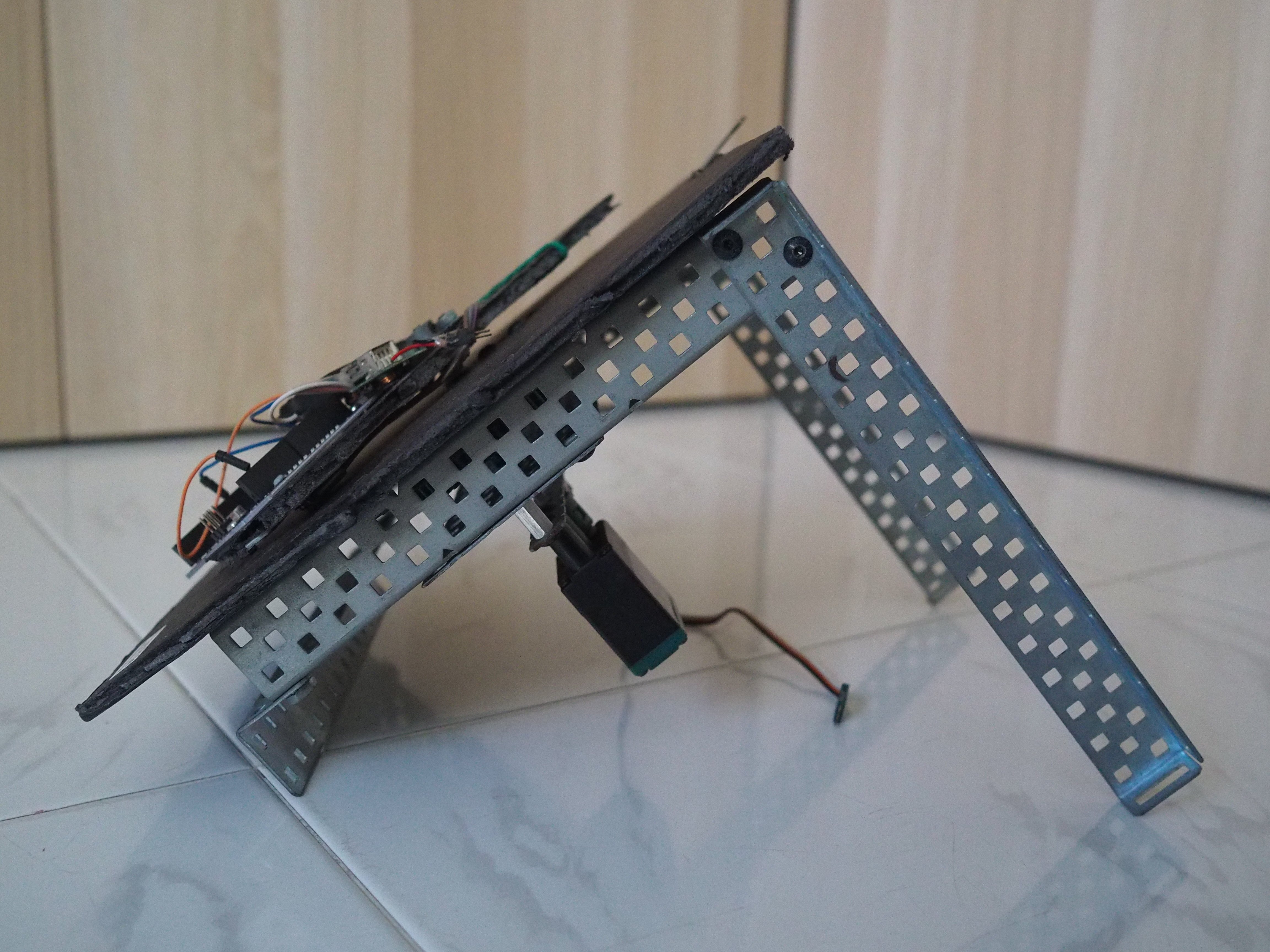
The next step would be to attach the micro-controller to some sort of beam or that will spin. For that, I used the parts from VEX to construct the base of the POV display, which would hold a motor to rotate the beam. The beam would be angled around 40 degrees, which makes the base more stable and the board easier to be seen.
The Stand
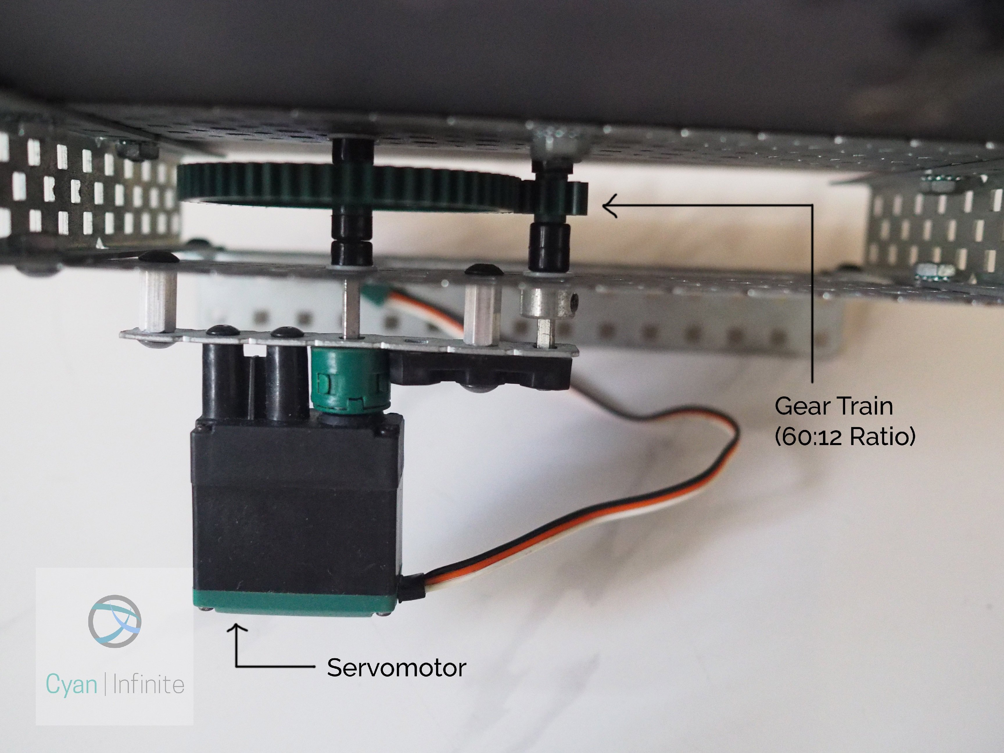
The stand would be used to hold the beam, and at the same time to spin the beam so as to generate the POV display. There is a servo motor mounted behind the stand, which is connected to a gear train (of 60:12 configuration) to increase the rotation speed. (Ideally a brushless motor would be better for high speed rotation, but it may cause some components, like the battery, to be flung out) The gear train outputs to a shaft, which would be connected to the beam. [Note: The Servo controller is not shown in the picture, but it is used to regulate the beams rotation velocity.]
Version #1
The first version of the POV stand is just a bare metal stand: nothing to cover the background of it. Other than that, a metal beam was used to hold both the MakerUno board and the power supply, with a gear mounted on the back of the beam. This design had many limitations, which includes:
- Inability to rotate fast due to the load and weight: The metal beam itself is not light, not to mention a powerbank attached to it.
- The beam is far from the center of the shaft, which increases the load of the servo: You can’t escape from the grasps of bending moment!
- Inconsistent rotation of beam: Due to the uneven distribution of weight, the beam will rotate faster/slower at certain point.
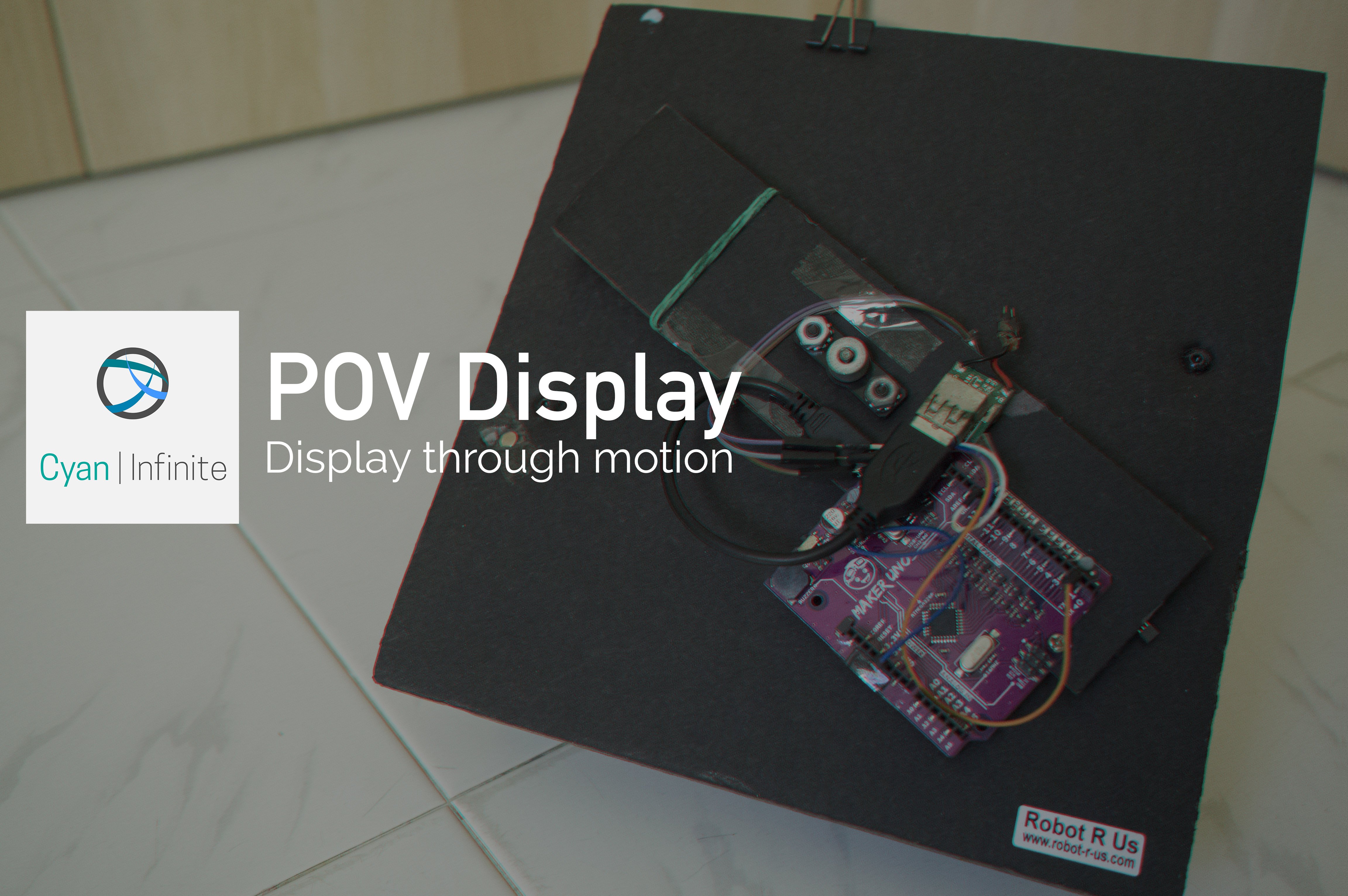
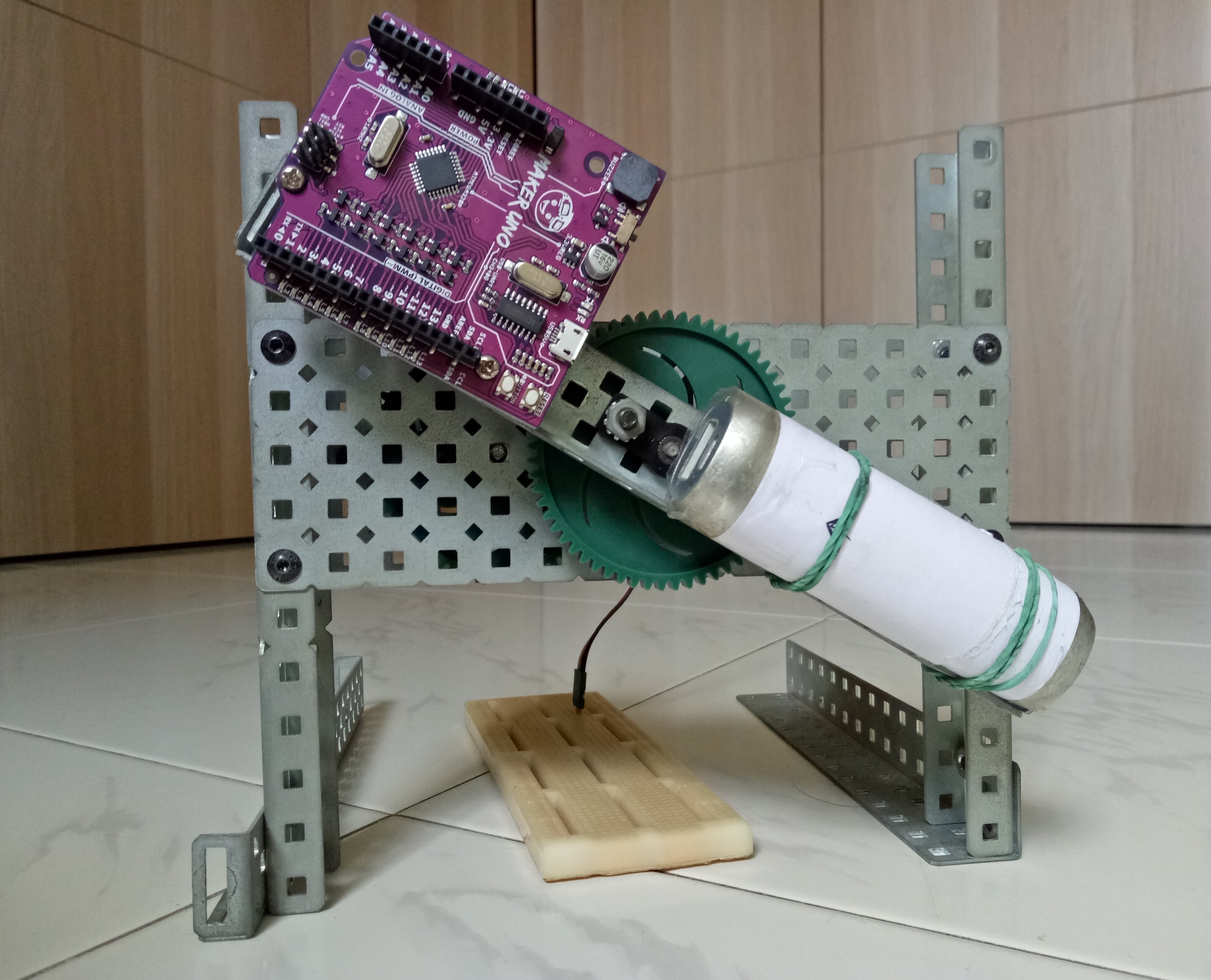
Version #2

Version #2 of the stand brought about a few improvements:
- Beam: Replaced from metal bar with gear to cardboard, which is much lighter. Other than that, the beam can be placed closer to shaft due to the removal of the support gear. (Hence reducing the bending moment, which makes rotating faster easier)
- Power supply: Changed from powerbank to LiPO with 5V regulator, which is adds to weight reduction.
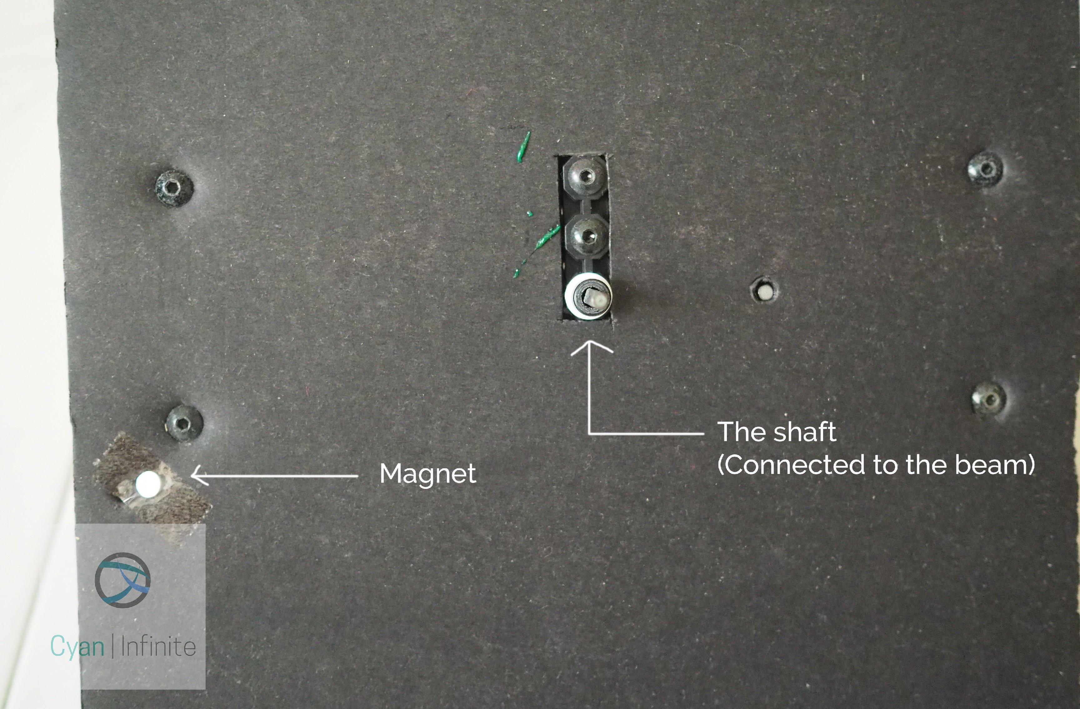
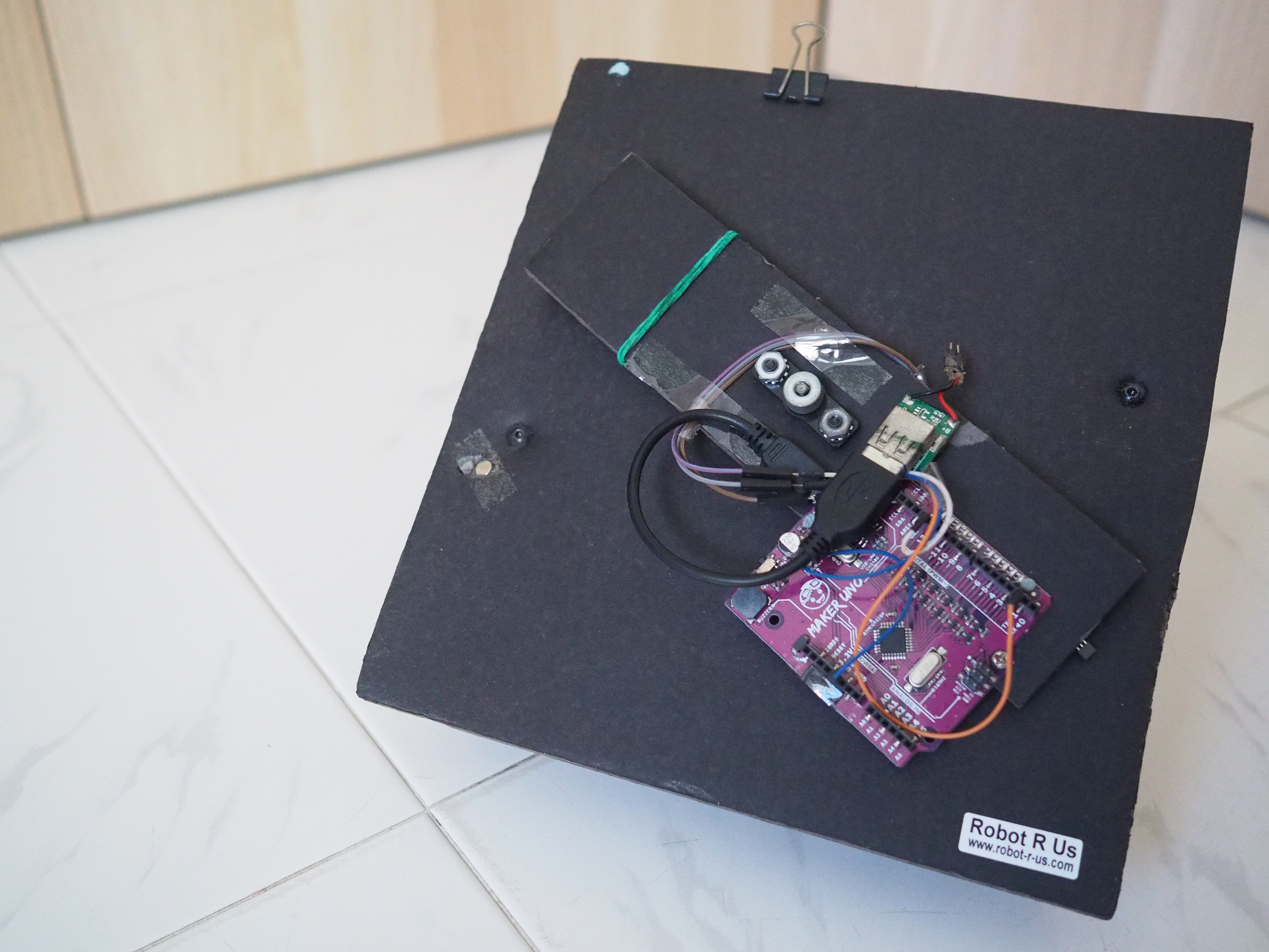
- Background: For the front part, a dark/black cardboard is mounted onto the body of the stand, with small opening for the shaft and to mount the servomotor into place. It makes the characters of the POV display more prominent as it contrasts the characters shown.
- Homing: On the southwest of the board, a neodymium magnet is inserted into the board. (Used as a homing point for the POV display).
- Stand placement: Rested the stand 45° instead of 90° for increased stability. (The stand occasionally moves due to the beam causing the whole structure to jerk)
Software
Moving on to the software side, we’ll have to figure out how do we display the POV. The tricky part of the POV display is when to turn on and off the LEDs at the different location/position of the rotating beam. For that, I got inspiration from the following website (https://blog.blinkenlight.net/experiments/basic-effects/pov-reloaded/), where the author explained his experience experimenting with POV. As the code is design for displaying a POV via the motion of a shaking hand, I have to modify it accordingly to suit our project.
Characters
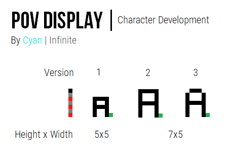
With 12 LEDs that we can utilized, I first experimented using 5 LEDs, with a length of 4 pixels for the charater & 1 blank pixel. (Making it a 5×5 character display) The characters (alphabets, numbers, some symbols) were constructed from scratch with the help of paint, which would later be translated into binary for the display. (The characters will be arranged in a “Height x Width” format.)
While experimenting, it was discovered that the 5×5 character was to small to be seen. Therefore, we experimented with a few other dimension (6×5, 7×7) before finalizing the characters to 7×5 and redesigning the characters, which improved the text display visibility. (The green dot pixel represents the blank column)
Parsing String
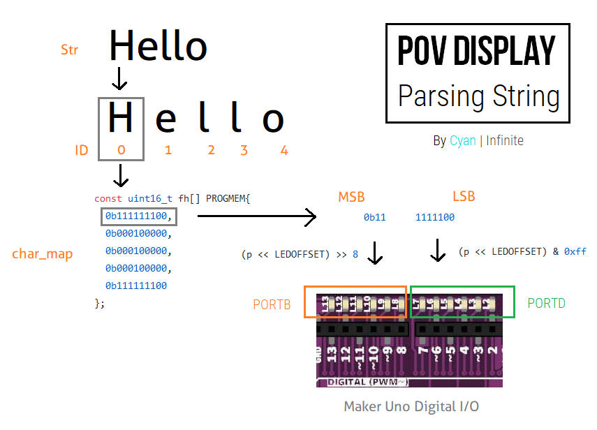
- Assign a string to be displayed.
- Split the strings up into individual characters.
- From the individual character, get the ASCII of the character and match it against the character/font map.
- If character exists: go through binary columns at specified character in font map.
- The column data (in binary) uses a word data type (2 bytes), it will be split into 2 parts:
- 1st half of data (Bit 0 [LSB] – Bit 7):
- Bitwise shift LEFT(<<) by OFFSET variable: To determine the starting point of the data
- Perform bitwise AND(&) operation of 0xFF
- Push to PORTD
- 2nd half of data (Bit 8 – Bit 15):
- Bitwise shift LEFT(<<) by OFFSET variable
- Shift RIGHT(>>) by : Removes 1stpart of the data
- Push to PORTB
- 1st half of data (Bit 0 [LSB] – Bit 7):
- The column data (in binary) uses a word data type (2 bytes), it will be split into 2 parts:
- Else: Display nothing (all LEDs off).
- If character exists: go through binary columns at specified character in font map.
- Move on to next character, repeat step 3.
- If the last character has been done parsing, display nothing. (End of line)
Synchronization
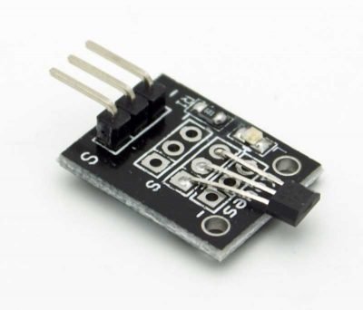
In order for the display to remain at a certain position, we would need some sort of marker to tell when to display what. (Without synchronisation, the display would appear to be spinning around due to the slight difference in the rotation speed) So to do that, we would be using a hall effect sensor (which detects magnetic field) to home the display. There are a few types of hall effect sensor (e.g. Analog, latching, etc), but we’ll be using the one that outputs a digital signal.
Components
- Maker Uno x 1
- Hall Effect Sensor x 1
- Power Source (LiPo Battery) + 5V Regulator x 1
- External beam x 1 (To mount the Arduino)
- Stand with Servomotor/Motor Base x 1 (To rotate the external beam)
Schematics
The connections are pretty straight forward: only 3 jumper wires are needed for the connection of the hall effect sensor. The power supply would be from a LiPo Battery, which would be connected to a USB 5V Regulator. A USB cable would be used to connect the 5V regulator to the Maker Uno board.
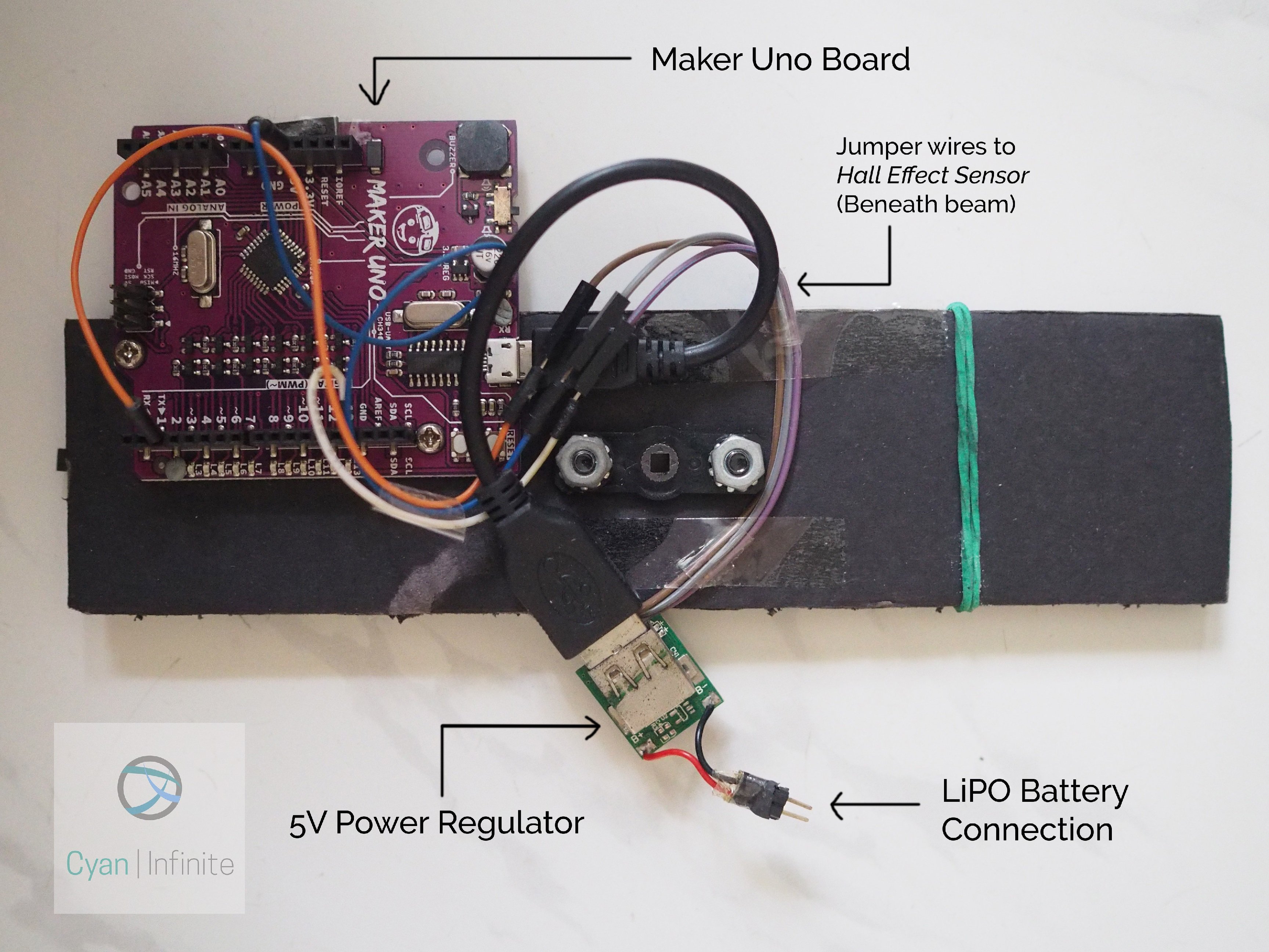
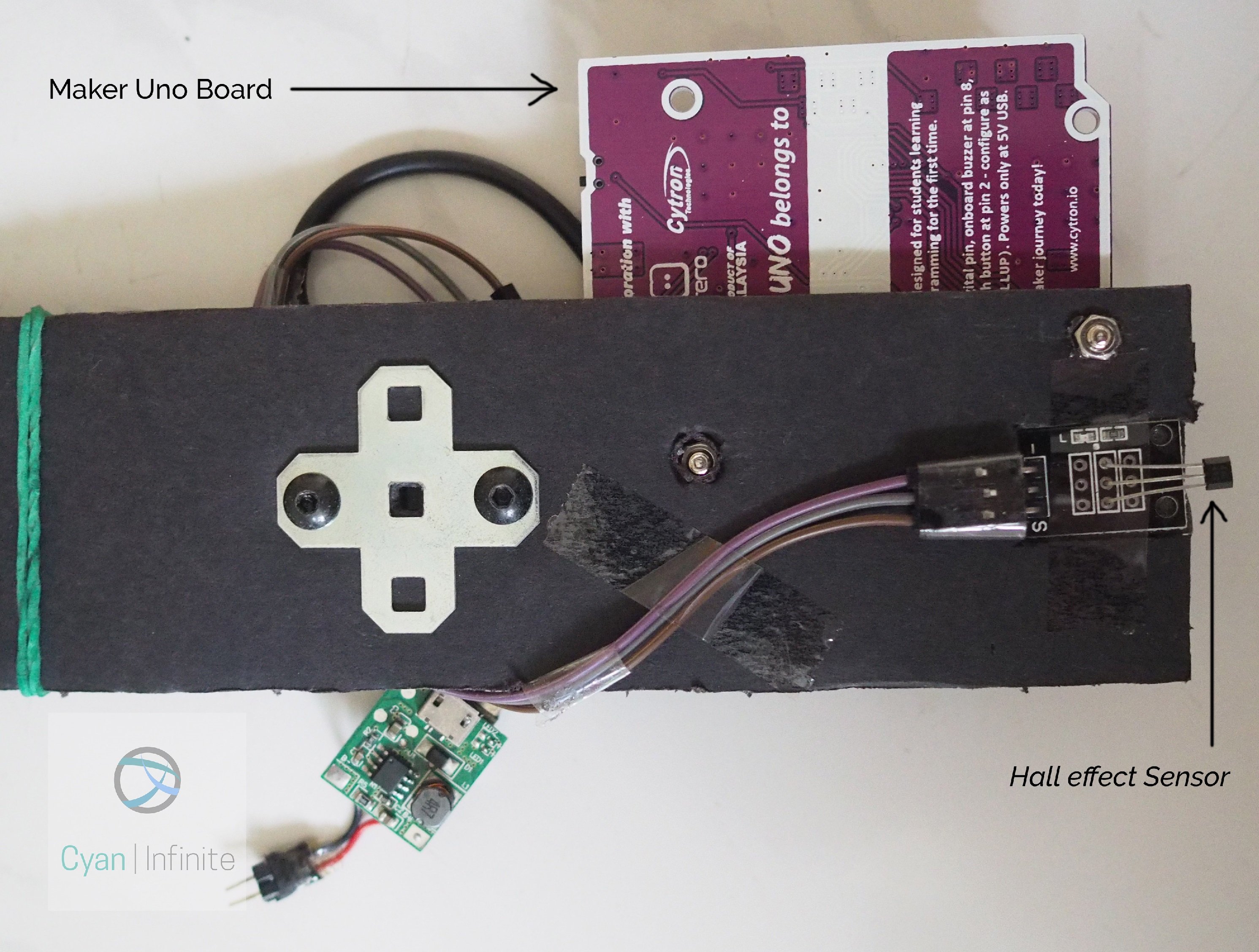
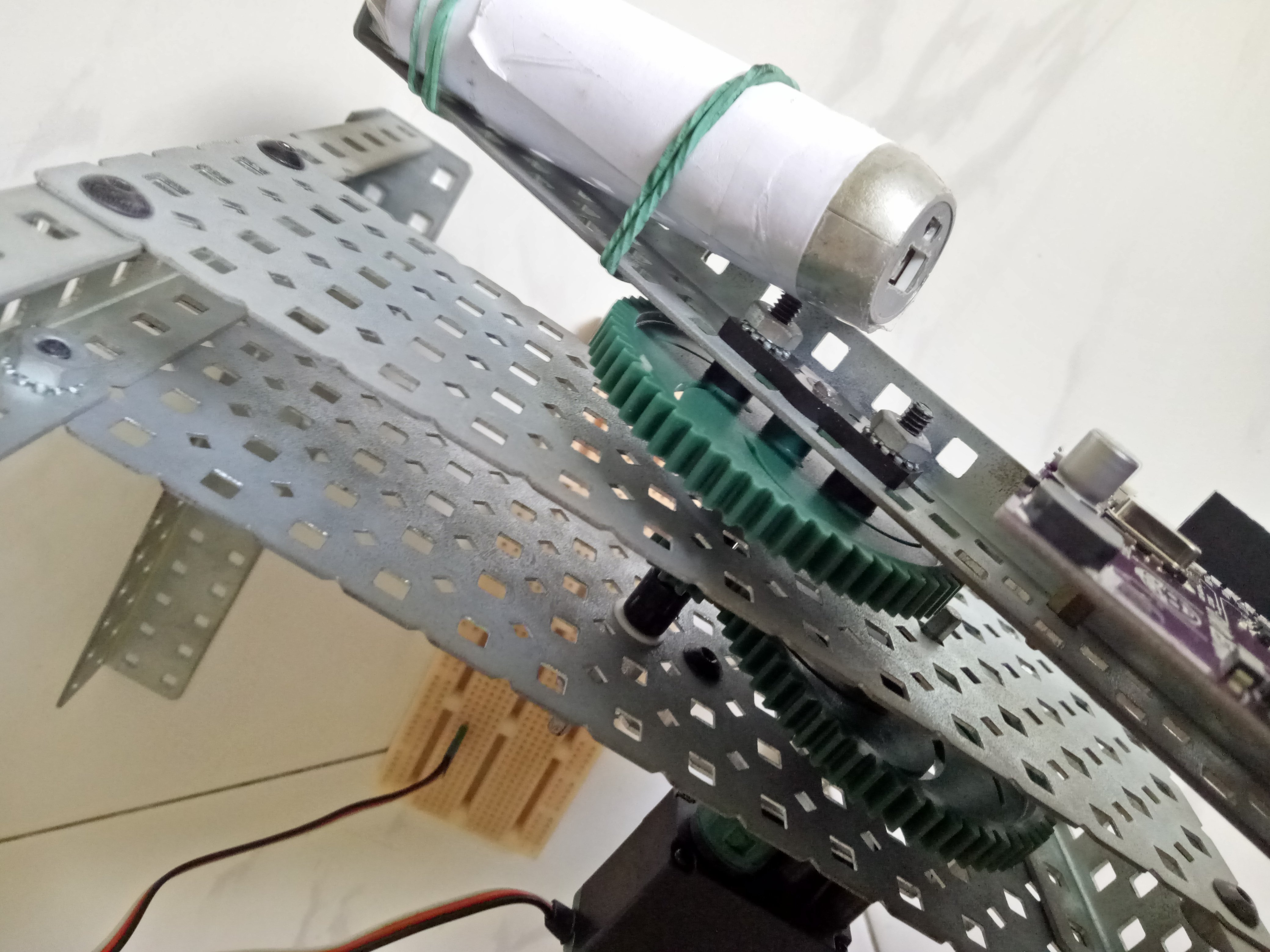
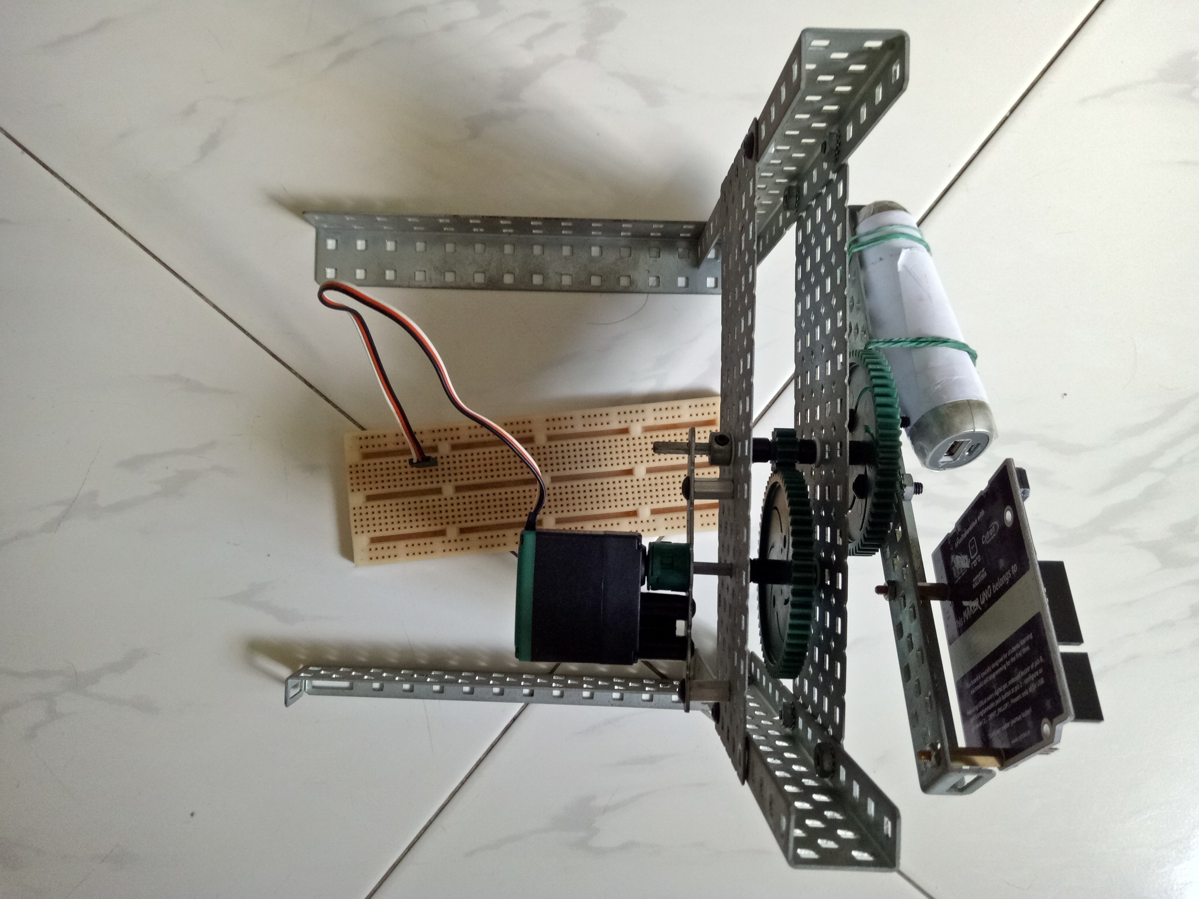
The Maker Uno board is mounted onto the board via 2 screws through the beam. The power regulator and the LiPO is then secured to the beam with a rubber band, which could be replaced with double-sided tape, Velcro strap,etc. in the future. (Not the best way to hold things firmly on a spinning beam, but it works)
Demo
Here are the following demos of the POV display of different iterations:
Iteration #1: Numbers
Iteration #2: Alphabet
Iteration #3: Text Display (2 Lines)
Issues
While working on the project, I was stuck at multiple occasion, below are a few of them.
- Got stuck somewhere & not sure on what to do
- Not sure how to proceed
- Random hardware issue
- Persistent bugs that seems to persist
Frequent shaking: Output shaft
As the shape of the hole of the metal beam (where the shaft exits from) & the shaft itself is square, the rotation of the shaft would not be smooth. (Have you seen a square wheel that moves smoothly?)
Solution: Placed a flat bearing (with a circular hole) to guide the shaft. This reduced the shaft from shaking too much, which increased the rotation velocity.
Frequent shaking: Main Base
As the beam that holds the components is made of metal, the weight of it is not small. Furthermore, placing a powerbank onto the beam adds more weight to the overall beam, making it bulky & imbalance. (The weight distrubtion is not uniform, which causes the base to move as it rotates at the powerbank section.)
Solution: Reduce the weight on the beam. To reduce the weight, the beam was changed to cardboard, and the power supply is changed from Power Bank to a LiPo Battery. (With a 5V regulator) This resulted in reduced shakiness and faster rotation. The stand is also tilted 45 degrees to make it more stable.
Inconsistent Display
The text does not remain in the same position: it rotates randomly occasionally. (One more thing, when I just started out, I was using the sample code provided here. The code was meant to be a hand shaken POV display, which was different from what I wanted to accomplished.)
Solution: Add a homing point whereby it determines the start/end point of one rotation. With this marker, the Maker Uno will know when one revolution is completed, which would allow the display to be updated accordingly. (For eample, adding a magnet & a hall effect sensor to synchronise the display)
Improvements
Even though most of the issues have been resolved in the final iteration, there are still many things that can be improved, which includes:
- Proper mounting of components (especially the battery & voltage regulator)
- Use of brushless motor: For higher speed and more consistent display
- Use of a lighter beam: Reduces vibration & shakiness of the stand
- Increasing display resolution by using more LEDs: Maybe a special PCB with more SMD LEDs on, without the need of a huge microcontroller board attached to the beam.
Conclusion
There are many takeaways from taking on this project, from learning how this type of (POV) display works to the appreciation of how things like displaying characters would require one to individually craft the description for the POV display. Even though the project got stuck multiple times (with no progress made), I finally managed to resolve each issue one at a time, eventually leading to the completion of the project. I also learnt how to utilize the low level operations to make better use of the microcontroller memory & lower the sketch size quite abit. Overall, it was fulfilling and enjoyable 3 months project that I worked on.
Code
This may be the part you have been waiting for! The code documented here is the final version of the code used to display 2 lines of text.
Alternatively, the code is available in Github.
mkuno-pov.ino: Main Sketch
/*
  ===========================================================
  Maker Uno POV Display, Sync with Hall Sensor
  Version 0.4.4
  By: 1487Quantum (https://github.com/1487quantum)
  ===========================================================
  > Uses moving average, with a period of 8
  > Reorganised code
  > Able to display alphanumeric chracters & some symbols (0-9, A-Z)
  Ref: https://blog.blinkenlight.net/experiments/basic-effects/pov-reloaded/
*/

#include "f7x5.h"
#include "MsTimer2.h"
#include "config.h"


//Ouput display colmn
//If upper set true, (upper bit) value would be returned
uint8_t fmt_pattern(bool upper, uint16_t p) {
  uint8_t q;
  if (upper) {
    //Shift by LEDOFFSET to left as LED starts from D2, not D0.
    //After that, Shift right by 8 to remove lower bits.
    q = (p << LEDOFFSET) >> 8;

  } else {
    //Lower half
    q = (p << LEDOFFSET) & 0xff; //Shift by LEDOFFSET to left as LED starts from D2, not D0
  }
  return q;
}

//#define sbi(port,bit) (port)|=(1<<(bit))  //To set pin state faster (only 2 cycles!)
//http://web.archive.org/web/20170819105819/http://www.atmel.com/webdoc/AVRLibcReferenceManual/FAQ_1faq_port_pass.html
void setTone(volatile uint8_t *port, uint8_t pin, uint8_t state) {
  //If port is PORTB, remove 8 as LSB starts at D8
  *port |= (state << pin - (*port == PORTB ? 8 : 0));
}

//Display string on POV
void dispMsg() {

  if (nmsg > 4000) {
    printMsg("     Hello world!  ");
  } else {
    printMsg(" This is a POV display ");
  }
  if (nmsg >= 8000) {
    nmsg = 0;
  }


  nmsg++;
  /*
    char charBuf[MAXCHAR];
    String buf = "RPM - ";
    buf += pd ;
    buf.toCharArray(charBuf, MAXCHAR);
    printMsg(charBuf);
  */
}


//Push the columns
//Font table, font element, column index
void pushCol(uint16_t *fnt[], uint16_t ch, uint16_t i) {
  if (DEBUG) {
    Serial.print(ch);
    Serial.print(F(","));
    Serial.print(i);
    Serial.print(F(","));
    Serial.println(pgm_read_word(fnt[ch] + i), HEX);
  }
  if (ch == -1) {
    //Turn off all LEDs
    PORTD = fmt_pattern(false, 0);
    PORTB = fmt_pattern(true, 0);
  } else {
    PORTD = fmt_pattern(false, pgm_read_word(fnt[ch] + i));
    PORTB = fmt_pattern(true, pgm_read_word(fnt[ch] + i));
  }

}

//Parse str -> char
void printMsg(char cmsg[]) {
  int char_k = 0;
  if (ch == strlen(cmsg) || ch >= MAXCHAR ) {
    //If msg end reach or char limit reach -> Blank the rest
    ch = -1;
    i = 0;
    done = 1;
  } else {
    char_k = cmsg[ch]; //Individual char ASCII
  }
  if (DEBUG) {
    Serial.print("Char: ");
    Serial.print(ch == -1 ? '~' : cmsg[ch] );
    Serial.print(",Blank: ");
    Serial.print(blank);
    Serial.print(",Done: ");
    Serial.println(done);
  }
  if (!done) {
    // make sure the character is within the alphabet bounds (defined by the font.h file)
    // if it's not, nothing will be displayed ('z'->122)
    if (char_k < 32 || char_k > 122) {
      char_k = 32;
    }
    //Convert lower to upper case if necessary
    // ASCII for a-z: 97-122
    if (char_k > 96 && char_k <= 122) {
      char_k -= 32;
    }
    // Converts ASCII num to the font index number
    if (char_k == 32 || blank) {
      pushCol(f_sym, -1, i); //Display nothing
    } else {
      //Check for symbols
      if (char_k > 32 && char_k <= 47) {
        char_k -= 33;
        pushCol(f_sym, char_k, i);
      } else {
        char_k -= 48;   //Since ascii for '1' is 49
        if (char_k > -1 && char_k < 10) {
          //Numbers 0 - 9
          pushCol(f_num, char_k, i);
        } else if (char_k > 15 && char_k <= 42) {
          //Alphabet A-Z, subtract 17 for alphabet font table
          pushCol(f_alp - 17, char_k, i);
        } else {
          //Display nothing
          pushCol(f_sym, ch, i);
        }
      }
    }

    if (i >= CH_WIDTH + CH_SPACE) {
      //All columns displayed, move to next char
      i = 0;
      blank = 0;
      ch++;

    } else {
      if (i >= CH_WIDTH - 1) {
        //Space between the char
        blank = 1;
      }
      //Mov to nxt column of char
      i++;
    }
  } else {
    //Display nothing
    pushCol(f_sym, ch, i);
  }

}


void setup() {
  if (DEBUG) {
    Serial.begin(115200);
  }
  // Leave pin 0 (serial receive) as input, otherwise serial port will stop working!) ...
  DDRD |= 0b11111010; // set digital  1,3- 7 to output, 2 as input (interrupt) [Safer way via or]
  DDRB = 0b00111111; // set digital  8-13 to output
  //Attach interrupt for hall sensor
  attachInterrupt(digitalPinToInterrupt(INT_PIN), updatePd, CHANGE);

  //Start display update timer
  MsTimer2::set(UPDATE_LED, dispMsg);
  MsTimer2::start();
}

void updatePd() {
  state = !state;
  //Rising edge would be time marker/trigger
  if (state) {
    unsigned long tmp_t = millis();             //Tmp var

    //long r_duration = tmp - lastUpdate; //raw duration

    //Duration of 1 rotation/revolution (in ms)
    //float s = int((tmp_t - lastUpdate) % 1000);
    pd = tmp_t - lastUpdate;
    pd %= 1000;
    lastUpdate = tmp_t;

    // Rotation in 1ms (ms/rev)
    //pd = 1/pd;
    if (DEBUG) {
      Serial.print("Pd:");
      Serial.println(pd);
    }

    //Refresh display
    dispMsg();
    ch = 0; i = 0; done = 0;
  }
}

void loop() {

}
config.h: Constants & Variables
#define DEBUG 0         //Enable to show serial log

#define INT_PIN 2       //Interrupt pin 2 for Hall sensor
#define S_PIN 8         //Buzzer pin hardwired to pin 8

//Display Settings
#define UPDATE_LED 0.0001  //Duration of LED "ON" per column
#define CH_WIDTH 5        //Num of columns in a single character
#define CH_SPACE 2        //Num of empty columns after single char
#define MAXCHAR 35        //Max num of char display
#define LEDOFFSET 3       //How many LED to offset from D0

//Test string
#define T_NM "0123456789 "                  //Numbers
#define T_AP "ABCDEFGHIJKLMNOPQRSTUVWXYZ"   //Alphabet (Upper)
#define T_SM "!"#$%'+,-./"                 //Symbols
#define T_HW "Hello world!"                 //Hello world

//tone track
uint16_t jc = 0; //Tempo counter
uint16_t tk = 0; //Tone counter
uint8_t snd = 0;  //Boolean to turn on sound

//Hall sensor var
volatile byte state = LOW;

//Timing var
unsigned long lastUpdate = 0;     //Time since last trigger
unsigned long pd = 1;             //Update Period (Duration for 1 revolution, ms)

//Display/font var
uint16_t ch = 0;  //char index
uint16_t i = 0;  //index i, step through width
uint8_t done = 0; //Is true when all char is displayed
uint8_t blank = 0; //Blank column would be shown if true


//Next msg counter
uint16_t nmsg = 0;
f7x5.h: Font Map
/*
==================================
7x5 FONT FILE
By: 1487Quantum
==================================
> Font description file for Maker Uno POV display, replaces "7x7.h".
> Consists of numbers (0-9), and letters (Capitalized, A-Z)
> Characters would be rotated 90 degrees clockwise.
==================================
CHANGELOG
==================================
v0.3.0
- Reduced font dimensions: 7x7 -> 7x5
- Removed last 2 rows of empty column
(Will be adding it dynamically via main fx)
- Shortened column data
v0.2.2
- Added symbols: ! " # $ % ' + , - . /
v0.2.1
- Changed numbers style (0-9)
v0.2.0
- Added alphabet (A-Z, Uppercase)
- Replaced "num6x5.h" with "f7x7.h"
v0.1.1
- Extended character space by 2 clumns instead of one
- Changed '4' style
- Added dscription
v0.1.0
- Initial Release
- Contains only blank & number characters (0-9)
==================================
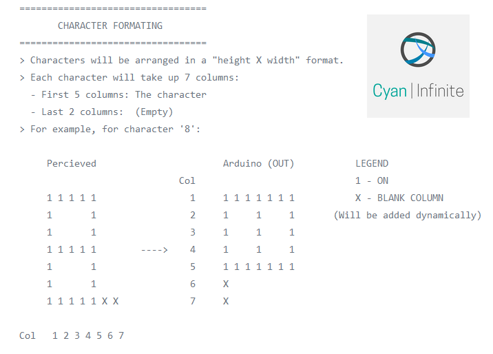
CHARACTER FORMATING
==================================
> Characters will be arranged in a "height X width" format.
> Each character will take up 7 columns:
- First 5 columns: The character
- Last 2 columns: (Empty)
> For example, for character '8':
Percieved Arduino (OUT) LEGEND
Col 1 - ON
1 1 1 1 1 1 1 1 1 1 1 1 1 X - BLANK COLUMN
1 1 2 1 1 1 (Will be added dynamically)
1 1 3 1 1 1
1 1 1 1 1 ----> 4 1 1 1
1 1 5 1 1 1 1 1 1 1
1 1 6 X
1 1 1 1 1 X X 7 X
Col 1 2 3 4 5 6 7
*/
//Symbols: ! " # $ % ' + , - . /
const uint16_t nnil[] PROGMEM{
0b000000000,
0b000000000,
0b000000000,
0b000000000,
0b000000000
};
const uint16_t s0[] PROGMEM{
0b000000000,
0b101111100,
0b101111100,
0b000000000,
0b000000000
};
const uint16_t s1[] PROGMEM{
0b000000000,
0b000011100,
0b000000000,
0b000011100,
0b000000000
};
const uint16_t s2[] PROGMEM{
0b001010000,
0b111111100,
0b001010000,
0b111111100,
0b001010000,
0b000000000
};
const uint16_t s3[] PROGMEM{
0b010010000,
0b010101000,
0b111111100,
0b010101000,
0b001001000
};
const uint16_t s4[] PROGMEM{
0b001000100,
0b000100000,
0b000010000,
0b000001000,
0b001000100
};
const uint16_t s5[] PROGMEM{
0b000000000,
0b000000000,
0b000011100,
0b000000000,
0b000000000
};
const uint16_t s6[] PROGMEM{
0b000100000,
0b000100000,
0b011111000,
0b000100000,
0b000100000
};
const uint16_t s7[] PROGMEM{
0b000000000, // 0x1FC
0b100110000,
0b100110000,
0b011110000,
0b000000000
};
const uint16_t s8[] PROGMEM{
0b000100000,
0b000100000,
0b000100000,
0b000100000,
0b000100000
};
const uint16_t s9[] PROGMEM{
0b000000000,
0b000000000,
0b100000000,
0b000000000,
0b000000000
};
const uint16_t s10[] PROGMEM{
0b000000000,
0b110000000,
0b001100000,
0b000011000,
0b000000100
};
//Numbers
const uint16_t n0[] PROGMEM{
0b111111100, //0x3f
0b100010100, //0x21
0b100100100,
0b101000100,
0b111111100
};
const uint16_t n1[] PROGMEM{
0b000000000,
0b100001000,
0b111111100, //0x1FC
0b100000000,
0b000000000
};
const uint16_t n2[] PROGMEM{
0b100001000,
0b110000100,
0b101000100,
0b100100100,
0b100011000
};
const uint16_t n3[] PROGMEM{
0b010001000,
0b100000100,
0b100100100,
0b100100100,
0b011011000
};
const uint16_t n4[] PROGMEM{
0b001100000,
0b001010000,
0b001001000,
0b111111100,
0b001000000
};
const uint16_t n5[] PROGMEM{
0b010111100,
0b100100100,
0b100100100,
0b100100100,
0b011000100
};
const uint16_t n6[] PROGMEM{
0b011111000, // 0x1FC
0b100100100,
0b100100100,
0b100100100,
0b011001000
};
const uint16_t n7[] PROGMEM{
0b000000100, // 0x1FC
0b000000100,
0b111000100,
0b000110100,
0b000001100
};
const uint16_t n8[] PROGMEM{
0b011011000, // 0x1FC
0b100100100,
0b100100100,
0b100100100,
0b011011000
};
const uint16_t n9[] PROGMEM{
0b000011000, // 0x1FC
0b100100100,
0b100100100,
0b010100100,
0b001111000
};
//ALPHABETS (UPPERCASE)
const uint16_t fa[] PROGMEM{
0b111111000,
0b000100100,
0b000100100,
0b000100100,
0b111111000
};
const uint16_t fb[] PROGMEM{
0b111111100,
0b100100100,
0b100100100,
0b100100100,
0b011011000
};
const uint16_t fc[] PROGMEM{
0b011111000,
0b100000100,
0b100000100,
0b100000100,
0b010001000
};
const uint16_t fd[] PROGMEM{
0b111111100,
0b100000100,
0b100000100,
0b100000100,
0b011111000
};
const uint16_t fe[] PROGMEM{
0b111111100,
0b100100100,
0b100100100,
0b100100100,
0b100100100
};
const uint16_t ff[] PROGMEM{
0b111111100,
0b000100100,
0b000100100,
0b000100100,
0b000100100
};
const uint16_t fg[] PROGMEM{
0b011111000,
0b100000100,
0b101000100,
0b101000100,
0b011001000
};
const uint16_t fh[] PROGMEM{
0b111111100,
0b000100000,
0b000100000,
0b000100000,
0b111111100
};
const uint16_t fi[] PROGMEM{
0b100000100,
0b100000100,
0b111111100,
0b100000100,
0b100000100
};
const uint16_t fj[] PROGMEM{
0b011000100,
0b100000100,
0b100000100,
0b100000100,
0b011111100
};
const uint16_t fk[] PROGMEM{
0b111111100,
0b000100000,
0b001010000,
0b010001000,
0b100000100
};
const uint16_t fl[] PROGMEM{
0b111111100,
0b100000000,
0b100000000,
0b100000000,
0b100000000
};
const uint16_t fm[] PROGMEM{
0b111111100,
0b000001000,
0b000110000,
0b000001000,
0b111111100
};
const uint16_t fn[] PROGMEM{
0b111111100,
0b000001000,
0b001110000,
0b010000100,
0b111111100
};
const uint16_t fo[] PROGMEM{
0b011111000,
0b100000100,
0b100000100,
0b100000100,
0b011111000
};
const uint16_t fp[] PROGMEM{
0b111111100,
0b000100100,
0b000100100,
0b000100100,
0b000011000
};
const uint16_t fq[] PROGMEM{
0b001111000,
0b010000100,
0b010000100,
0b010000100,
0b101111000
};
const uint16_t fr[] PROGMEM{
0b111111100,
0b000100100,
0b000100100,
0b000100100,
0b111011000
};
const uint16_t fs[] PROGMEM{
0b010011000,
0b100100100,
0b100100100,
0b100100100,
0b011001000
};
const uint16_t ft[] PROGMEM{
0b000000100,
0b000000100,
0b111111100,
0b000000100,
0b000000100
};
const uint16_t fu[] PROGMEM{
0b011111100,
0b100000000,
0b100000000,
0b100000000,
0b011111100
};
const uint16_t fv[] PROGMEM{
0b000111100,
0b011000000,
0b100000000,
0b011000000,
0b000111100
};
const uint16_t fw[] PROGMEM{
0b001111100,
0b110000000,
0b001110000,
0b110000000,
0b001111100
};
const uint16_t fx[] PROGMEM{
0b110001100,
0b001010000,
0b000100000,
0b001010000,
0b110001100
};
const uint16_t fy[] PROGMEM{
0b000001100,
0b000010000,
0b111100000,
0b000010000,
0b000001100
};
const uint16_t fz[] PROGMEM{
0b110000100,
0b101000100,
0b100100100,
0b100010100,
0b100001100
};
// Font table - Symbols
const uint16_t *f_sym[] {
s0, s1, s2, s3, s4,
nnil, s5, nnil, nnil, nnil, s6,
s7, s8, s9, s10
};
// Font table - Num
const uint16_t *f_num[] {
n0, n1, n2, n3, n4,
n5, n6, n7, n8, n9
};
// Font table - Alphabets (Uppercase)
const uint16_t *f_alp[] {
fa, fb, fc, fd, fe, ff, fg, fh, fi,
fj, fk, fl, fm, fn, fo, fp, fq, fr,
fs, ft, fu, fv, fw, fx, fy, fz
};